Introduction
Capstans are frequently deployed mooring equipment used on all types of vessels. Capstans are berthing/mooring equipment used to multiply the pulling force on mooring ropes.
Traditionally, Capstans were operated manually but in modern ships, they are operated wither electro-hydraulically or electromechanically.
When Capstans are used in mooring ships, they have to be sufficient in size and number to overcome the forces which the ship experiences in the lateral direction due to environmental forces of wind and current. How do we know what size capstans will be sufficient? We’ll take a detailed look at in this article.
This article is based on DDS-582-1 Calculations for Mooring Systems, Department of the Navy, Naval Sea Systems Command, Washington DC, 20362-5101.
The Concept
When berthing a vessel, a number of capstans on the vessel may be utilized simultaneously. How do we determine if the capstan size is sufficient?
Thinking in basic terms, the berthing operation of the vessel will impose some forces on the vessel, which are transferred through the berthing lines to the capstans. What forces are these?
At the berth, the two major forces are the wind and current forces that the vessel experiences. Also, since the vessel is mostly berthed sideways, these forces must be calculated on the side of the vessel (not on the front).
The wind and current forces are characterized by the wind and current speed at the berth.
Thus, a simple approach to determine the capstan design will be:
- Calculate the lateral berthing forces (wind and current) on the vessel
- Divide the total lateral berthing force by the number of capstans to get the force per capstan. This will give the required line pull of the capstan
- The capstan power is obtained by dividing the required line pull times the warping speed by the capstan’s efficiency.
Environmental Forces
The first step is calculating the environmental forces on the vessel. Generally, at berth, wind, and current are the most significant forces, while wave forces can be generally ignored.
When calculating the wind and current forces, the standard physics formula of Force = Pressure x Area shall be used. In the method by DDS-582 (Ref 3), wave forces have not been considered for doing the calculation.
For wind force, the formula is Fwind = 1/2 x Cwind x ρwind x Vwind2 x Awind, where Cwind is the coefficient of wind force, ρwind is the density of air, Vwind is the wind speed, and Awind is the total area of ship and cargo which is exposed to the wind from beam direction (the above-water area)
Similarly, for current force, the formula is Fcurrent = 1/2 x Ccurrent x ρwater x Vcurrent2 x Aunderwater, where Ccurrent is the coefficient of current force, ρwater is the density of water, Vcurrent is the current speed, and Aunderwater is the total underwater area of ship which is exposed to the current from beam direction.
The critical items in the calculations for Wind and Current forces are the force coefficients for wind and current.
These coefficients can be obtained from the coefficient plots provided in DDS-582, and some plots are presented below:
 L
L
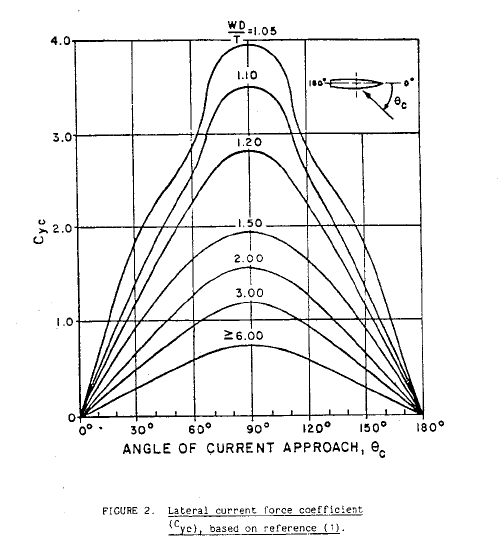
Lateral Current Coefficient (DDS-582)
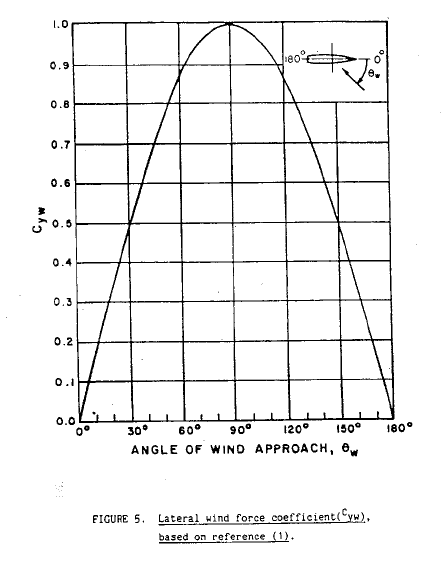
Lateral Wind Coefficient (DDS-582)
We can see that the lateral current force is dependent on an additional factor: the underkeel clearance which is measured as Water Depth to Draft ratio (WD/T).
At the end of this exercise, we’ll have the following with us:
- Wind Force – transverse
- Current force – transverse
Next exercise is using these forces and calculate the capstan line pull using the environmental forces.
Capstan Design
Once we have the wind and current lateral forces, we add them up together to give the total lateral force on the vessel.
Total Lateral Force, FY = FYW + FYC, where
FY = total lateral force on the vessel
FYW = lateral wind force on the vessel
FYC = lateral current force on the vessel
If the number of capstans is ‘n’, then the line pull per capstan is given by:
PCP = FY/n
Once the line pull is available, the minimum required Capstan power is determined as follows:
PCAPSTAN = PCP x VCP/ηCAPSTAN
Here,
PCAPSTAN = Required minimum capstan power
VCP = Capstan’s warping line speed
ηCP = Capstan’s efficiency
The Capstan’s efficiency has the following components:
- Capstan Head Efficiency
- Overall bearing and gear efficiency
- For electro-hydraulic capstans additionally – Efficiency of Hydraulic Pump and Motor
From the above process, we can obtain the minimum required Capstan’s power using which we can select the right capstan, or we can evaluate the suitability of an existing capstan for berthing.
TheNavalArch has its own app for selecting the right capstan. Do check it out from the link below.
References
- https://en.wikipedia.org/wiki/Capstan_(nautical)
- https://www.brighthubengineering.com/seafaring/51281-what-is-a-capstan-on-a-ship/
- DDS-582-1 Calculations for Mooring Systems, Department of the Navy, Naval Sea Systems Command, Washington DC, 20362-5101
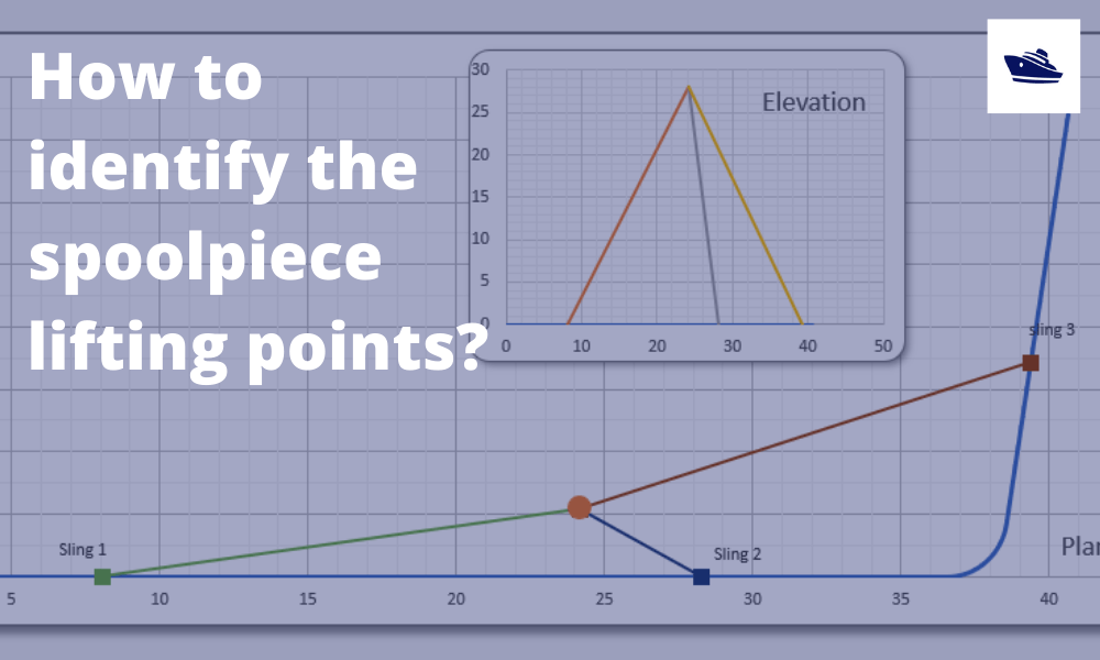
How to identify the spoolpiece lifting points?
In the offshore construction industry, the connection between the newly installed pipeline and the riser is accomplished via a series of ‘spoolpieces’ (or spools). The spool is fabricated by welding pipe joints to form an L-shaped, Z-shaped, or possibly a straight...

The importance of clear decision support before marine operations
Our oceans are interspersed with human activities: be it fishing, marine transportation, or offshore operations. These operations usually involve assets worth multiple million dollars, be it the produce or the equipment or in most cases, the human life. Produce from...
Sea Pressure Loads Calculation based on DNV Rules
Introduction Sea pressure loads are an important factor in the structural design of a vessel. What is sea pressure load? As the term suggests, it is the external pressure on the vessel due to the surrounding sea. What kind of pressure it is, and how to...
A quick empirical method for resistance estimation of planing vessels
Resistance estimation for a vessel is a fundamental exercise in design of the vessel. Resistance is a property that depends on the vessel’s shape and form. A conventional ship-shaped vessel with a bulb will have completely different resistance characteristics compared...
Powering the maritime industry with Hydrogen – Part 2
Powering the shipping industry with hydrogen - Part 2: Hydrogen propulsion on a ship - opportunities and challenges Introduction In the Part 1 of this article, we explored the basic properties of Hydrogen as a fuel, and also the opportunities and challenges...
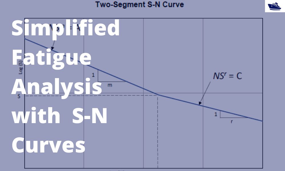
A simplified method of performing fatigue analysis of offshore structures
A simplified method of performing fatigue analysis of offshore structures Introduction An offshore structure is subject to environmental loads of waves, wind and current. By their nature, the resulting wave loads on the structure are cyclical. These cyclical...

Powering the shipping industry with hydrogen: opportunities and challenges (Part 1)
Part 1: About Hydrogen – Basics, Opportunities, and Challenges Of late, hydrogen has been generating quite a buzz in the energy sector with its possibility as a clean source of energy. The shipping sector is not untouched, and this article explores the possibilities...

Vessel Draft Survey Accuracy
by Chris Zeringue, Owner, MTS Marine Techincal Surveyors The key to accuracy in a Vessel Draft Survey may very well be found in a hole in the ship. I boarded my...
How to use a ship’s hydrostatics to calculate its draft and trim
Introduction A ship’s hydrostatics, or hydrostats, is an oft used term in maritime parlance, and it refers to the characteristics when it is floating. What characteristics are these? How are these determined, and how can we read and understand them? Understanding...
Numerical integration methods for hull volume estimation
Introduction The hull of a ship is a complex 3D geometry, and finding out its simple properties like volume, centroid, etc. is not possible through simple formulae unlike standard shapes like cuboid or a cylinder. How do we find a property, say the volume of a...
Work as a Project Engineer at Colombo Dockyard PLC for New Building Projects