OFFSHORE INSTALLATION VESSELS STABILITY CONSIDERATIONS
By Alan Crowle, BSc, MSc, MScbyRes, CEng, CMarEng, FRINA, FMAREST, FSCMS
University of Exeter, College of Engineering, Renewable Energy Group
INTRODUCTION
The temporary phases of an offshore structure transport require a specialised vessel. The transport vessels may be powered, for example a Heavy Transport Vessel (HTV) or require towing, a cargo barge. Intact stability, both GM and GZ curves, and damage stability need to be considered. This article outlines the temporary phase definition, marine warranty requirements, typical transport vessels, incidents and stability enhancement. This article covers project cargo used for onshore modularisation projects, renewable (in particular transformer substations) for offshore wind farms, offshore modules and floating cargo.
TEMPORARY PHASES
Loadout
Loadout is the movement of the Cargo from a construction yard onto a transport vessel.
Input requirements for the Loadout quay are:
- Loadout method by Skidding or Self-propelled modular transporter (SPMT) or Lifting
- Quay height above lowest astronomical tide (LAT)
- Water depth at the Loadout quay relative to LAT
- Tidal range, highest astronomical tide (HAT) to LAT
- Mooring bollards on the quay
- Mooring winches on the quay
- Lightship weight and Centre of gravity (CG)
Input requirements for the ocean transport vessel are:
- Cargo weight and Centre of gravity (CG)
- Upper grillage weight and CG
- Ballast tank arrangement
- Ballasting method on the transport vessel, which can use vessel pumps or an external ballast system
- Mooring bollards on the transport vessel
- Lightship weight and CG
Loadout stability criteria are measured by the metacentre above the centre of gravity (GM):
- Transport vessel stability has to be adequate throughout the Loadout operation.
- Loadout minimum GM is to be 0.15m, but a more realistic minimum GM of 1.0 m is expected
- The GM calculation must include free surface effects
- A Loadout where there is a significant friction force between the transport vessel and the quay wall
- Cases where a change of wind velocity may cause a significant change of heel or trim
During a Loadout other marine traffic is kept away, thus minimising the possibility of collision and waves overtopping the deck of the transport vessel when it is at low freeboard. The under keel clearance, during Loadout, is to be at least 1.0m, thus minimising the possibility of grounding.
The effective freeboard during the Loadout shall always be greater than 0.5 m plus 50% of the maximum wave height expected during the Loadout operation. The effective freeboard allows for the maximum possible tide level during the Loadout period. The bunding of openings in the transport vessel deck is required for low freeboards. Normally, there is no requirement to document damage stability during Loadout. However, consideration of /how incorrect operation of the ballast system may influence stability is to be checked.
If the load line is exceeded, then the minimum freeboard used during the Loadout operation is confirmed as acceptable by the transport vessel’s class society and is to be sufficient to maintain the transport vessel’s water plane area. The Loadout is carried out in wind speeds less than 10m/s and significant wave heights less than Hs=0.5m
Ocean Transport Vessel
Input requirements during ocean transport and coming alongside the offshore installation vessel:
- Cargo weight, CG and radii of gyration
- Upper grillage weight, CG and radii of gyration
- Lower grillage weight, CG and radii of gyration
- Seafastenings weight, CG and radii of gyration
- Ballast tank arrangement
- Ballasting methods
- Minimum water depth on the ocean route
- Air draft restriction, bridges and power cables
- Width restriction, locks and canals
- Lightship weight, CG and radii of gyration
Ballasting constraints are considered:
- Ensure sufficient intact and damage stability
- Trim angle is less than 1%
- Heel angle is zero
- Minimise motions and accelerations on the cargo.
- The natural roll period should be away from the expected wave periods
- Longitudinal shear forces and bending moments are within allowable
- Local strength is acceptable.
- Lower grillage is required to spread the loads from the cargo into the deck of the transport vessel
- Minimise powering requirements for HTV or the towing tug
Intact Stability, the transverse metacentric height (GM) must be 0.15m and preferably 1.0m, at zero angle of heel. Correction to values of GM to allow for free surface effects is to be included in this calculation. The application of free surface corrections to reduce metacentric height (GM) and hence to increase natural roll period will not generally be accepted. The effect of any reduction in GM due to free surface effect is to, be considered in intact and damage stability calculations.
The intact stability, or intact range of stability, shown in Figure 1, is the range between 0º heel or trim and the angle at which the righting arm (GZ) becomes negative
Figure 1: Righting Arm
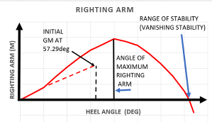
In the event of the range of static stability being greater than 30 degrees and less than 40 degrees, it is to be demonstrated that the maximum predicted roll angle is less than the angle at which the maximum righting lever occurs, as referenced ISO 19901-6:2009 Marine operations.
The stability range should not be less than where no motion data is available = 20 + 0.8*θ, where θ is the sum of the static wind heeling angle and the maximum roll angle in degrees. Where cargo overhangs are immersed as a result of heeling due to a 15 m/s beam wind in still water conditions, it is demonstrated that transport vessel control is not seriously impaired, and that no structural damage to the cargo can occur.
For marine operations of very short duration in sheltered waters (for instance, harbour moves and out-of-dock operations) that are covered by a reliable weather forecast, an exemption from the intact stability requirements may be considered. However, the stability range must never be less than 15°.
Alternatively, for barges, referenced in NVGL-ST-N001 Marine Operations, if maximum amplitudes of motion for a specific towage or voyage can be derived from model tests or motion response calculations, the intact range of stability is not less than = 15 + (15/GM) + θ
Where GM is in metres and θ = the maximum amplitude of roll or pitch caused by the design seastate plus the static wind heel or trim caused by the design wind, in degrees. A range of static stability less than 30 degrees is not normally accepted.
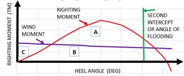
Intact Dynamic Stability, Figure 2, considers the areas under the righting moment curve and the wind heeling moment (or wind moment) curve is calculated up to an angle of heel, which is the least of:
- The angle corresponding to the second intercept of the two curves
- The angle of down flooding
- (area-A + area-B) greater than 1.4 * (area-B + area-C)
Figure 2: Intact righting moment curve
The wind velocity used to compute the wind heeling moment curve should be the 1-minute sustained wind for the operation with return periods. The duration is the tow time plus the worst-case waiting on weather at the offshore installation site. The default return period is 10 years; see Table 1 for shorter voyages.
.
Table 1: Significant wave return period for different voyage lengths
|
DURATION OF VOYAGE |
DESIGN WAVE AND WIND CRITERIA |
|
|
Up to 3 days |
Specific monthly weather criteria |
|
|
3 days to 1 week |
1-year return period and seasonal |
|
|
1 week to 1 month |
10-year return period and seasonal |
|
|
1 month |
10-year return period, seasonal |
|
|
Seasonal = summer, autumn, winter or spring |
||
Assume the wind velocity used to compute the overturning moment curve should be 36 m/s (70 knots) if no data is available. Damage stability, as a minimum, the transport vessel should have sufficient stability and reserve buoyancy to remain afloat at a waterline below any opening where progressive flooding may occur with any one compartment adjacent to the sea flooded. Damage to any compartment above the intact waterline that can lead to loss of stability is considered when assessing damage stability. The loss of water from a full compartment is considered if it gives a more severe result than the flooding of an empty compartment.
The areas under the righting moment curve and the wind heeling moment curve are calculated from equilibrium up to an angle of heel which is the least of:
- The angle corresponding to the second intercept of the two curves
- Or the angle of down flooding
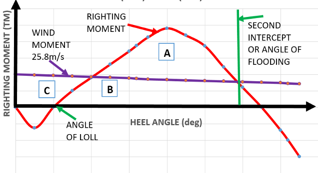
The wind velocity used to compute the overturning moment curve is 25.8 m/s (50 knots). Where it is impracticable to comply with damage stability recommendations, a hazard risk assessment (HAZID) is carried out, and appropriate mitigating measures are taken. If buoyancy of the cargo has been included to meet intact stability requirements, then loss of cargo buoyancy or flooding of cargo compartments, shall be considered as a damage case, as appropriate. Typical damage stability is shown in Figure 3. There is a negative GM at the zero heel angle. The damage stability requirements depend on the transport vessel, the voyage route and whether a summer or winter voyage is envisaged
Figure 3: Damage righting moment curve
Allowable VCG curve
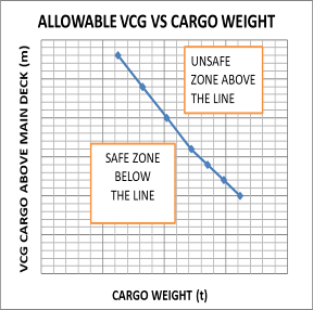
The allowable VCG curve, Figure 4, for the transport vessel is used to understand the stability restrictions. It combines the requirements of intact and damage stability.
Figure 4: Typical allowable VCG curve
Ocean Transport Vessel for floatover
Input requirements are during ocean transport and coming alongside the offshore installation vessel:
- Cargo weight, CG and radii of gyration
- Upper grillage weight, CG and radii of gyration
- Lower grillage weight, CG and radii of gyration
- Seafastenings weight, CG and radii of gyration
- Ballasting methods
- Minimum water depth at the installation
- Under keel clearance
Transport vessel stability has to be adequate throughout the floatover installation operation, namely:
- Stability checks are carried out for the full range of probable GM values
- A small metacentric height, may induce a heel or trim during the ballasting/weight transfer
- Cases where a change of wind velocity or wave direction may cause a significant change of heel
- During float-over installation, it is necessary to maximise float-over clearance
- For this case, only intact stability needs be considered with a positive GM of 1.0m
- Down flooding points should be above wave crest heights after allowing for run-up.
It is assumed that the minimum required GM is 1.0m at all stages of the floatover, after the effects of free surface have been considered. It is assumed that there is always 1.0m of under keel clearance during all stages of floatover. The stability of the vessel during the floatover, especially in the case of a ballasting malfunction, is to be considered.
The maximum draft of the installation/removal barge during float-over shall not exceed the maximum loadline draft, without a class exemption (but this is not normally needed for semi-submersible heavy transport barges or vessels). For operations involving semi-submersible barges or heavy transport vessels with watertight main decks, wave crests may be allowed to overtop the vessel deck, provided that all hatches and down flooding points are suitably protected and that raised walkways are added to all areas affected by water on deck where personnel movement is required.
The minimum freeboard is defined as the minimum distance from the waterline to the watertight deck level after accounting for static trim and heel. The minimum freeboard shall be sufficient to maintain the vessel’s water-plane area and to ensure sufficient stability range at all stages of the operation; the minimum freeboard is to be at least 1.0m. A lower minimum freeboard may be acceptable if adequate precautions and procedures are in place to ensure that the stability of the vessel is maintained. The minimum freeboard used during the operation shall be confirmed with the barge owner.
Examples of permeability to be used in damage condition:
- Living Space = 95%
- Machinery Space = 85%
- Ballast tank = 99%
TYPICAL TRANSPORT VESSELS
Cargo barges
Cargo barges have no propulsion and so need ocean tugs to tow them offshore.
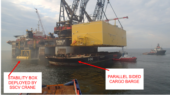
Parallel-sided barges are used to transport deck cargo. The Loadout is usually over the stern. See Figure 5, which shows a parallel-sided cargo barge.
Figure 5: Parallel sided transport vessel (Credit McDermott)
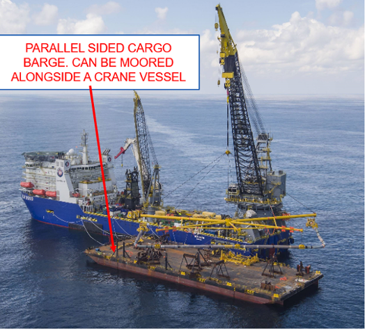
Parallel-sided cargo barges are fitted with skid rails for launching jackets. The Loadout is over the stern.
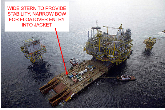
T-shaped barges are designed to transport modules for floatover operations, Figure 6. The stern is much wider than the bow. These barges are fitted with skid rails, originally for launching jackets, but later for moving modules for floatover from the barge deck. The Loadout is only over the stern. See Figure 6, which shows shaped barges. Floatover installation is a method for assembling offshore platforms by floating heavy decks or topsides over a barge and gently lowering them onto a pre-installed substructure.
Figure 6: T shape barge (Credit McDermott)
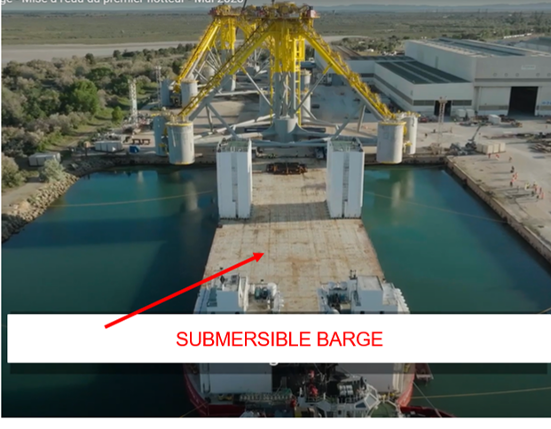
Submersible barges, Figure 7, are designed for loading or off loading floating cargo such as semi submersibles or jack-ups. They can also be used to transport dry deck cargo. Loadout can be over the stern or side. Floating discharge is in shallow water, as the stern will rest on the seabed.
Figure 7: Submersible barge, no accommodation (Credit SBM)
Heavy transport vessels (HTV)
Heavy transport vessels have self-propulsion. Some may have Dynamic Positioning (DP 2) systems, which enable them to take advantage of heading control and reduced beam wave heights in beam seas. Types of HTV are:
- Geared HTV, with cranes, cargo carried on deck and in the holds
- Module Carrier HTV, cargo carried only on the flat deck
- Double-ended HTV, can submerge the main deck. Cargo only on the flat deck
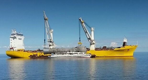
Geared HTVs are fitted with high-capacity cranes. Loadout is by crane, see Figure 8. They may be fitted out with stability pontoons, which are deployed on the crane side of the Geared HTV, during lifting operations.
Figure 8: Geared HTV (Credit Biglift)
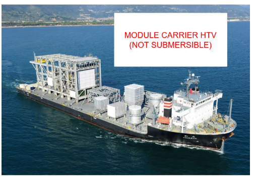
Module carrier HTV, Figure 9, cannot be submerged and is suitable only for dry deck cargo. Loadout is generally over the stern, by SPMT or skidding.
Figure 9: Module Carrier HTV (Credit NYK)
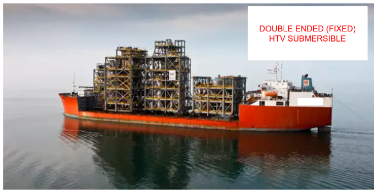
Double-ended HTV (main deck submerging) Figure 10, are designed primarily for loading or off loading of floating cargo, and in this case the main deck can be submerged. Where a dry cargo is transported the Loadout is over the side for large cargoes, and the stern Loadout for smaller cargoes.
Figure 10: Double ended HTV Fixed Buoyancy Tanks (Credit Boskalis)
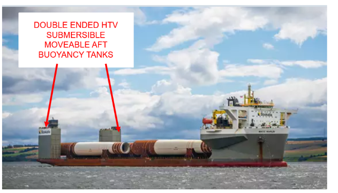
Double-ended HTV, Figure 11, can be used for loading or off-loading of floating cargo when fitted with stern buoyancy tanks. If the buoyancy tanks are removed from the stern, then the HTV can be used for transporting dry cargo. The cargo can be loaded over the side in moderate tidal ranges of less than 2.5m. Stern Loadout is possible assuming the stern is of sufficient strength.
Figure 11: Double-Ended HTV with Movable Stern Buoyancy Tanks (Credit Boskalis)
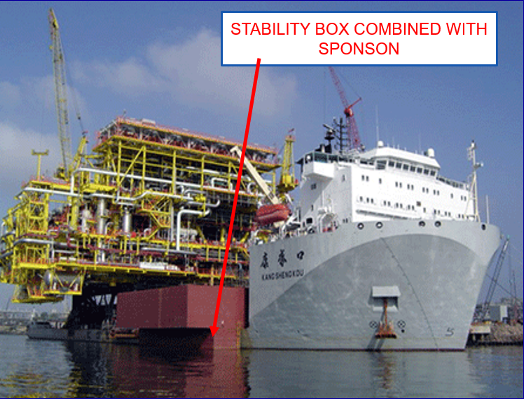
Sponsons
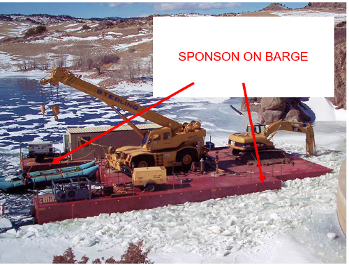
Sponsons tanks provide buoyancy and stability enhancement. Sponson Tanks, Figure 12, are projections from the sides of a vessel and they act for protection, stability, or mounting of equipment. They extend a hull dimension at or below the waterline and serve to increase flotation or add lift when underway.
Figure 12: Sponsons added (credit Flexifloat)
Advantages
- Cheaper than a new build vessel
- Sponsons specific to marine task
Disadvantages:
- Increased transport vessel weight
- Dry docking to fit the sponsons
- Dry docking to remove the sponsons
- Increased drag, slower steaming speed
- Scrapped after use
Stability boxes
Stability boxes, provide stability enhancement during ocean transport. The transport vessel does not need to be dry docked to fit or remove stability boxes. See Figure 13, which shows how stability boxes improve range of stability, as they are above the still water line.
Figure 13: Stability boxes on the main deck (Credit Cosco)
Advantages
- Cheaper than a new build vessel
- Sponsons specific to the marine task
Disadvantages:
- Increased transport vessel weight
- Scrapped after use
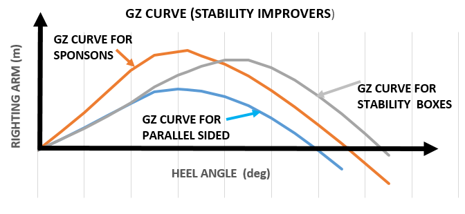
Comparison stability improvers
The sponsons increase in a higher initial GM and improved range of intact stability, see Figure 14. The transport vessels with Stability boxes have a slightly lower GM than the base vessel, because of the local VCG of the boxes. But the intact range of stability is larger than that using sponsons.
Figure 14: Typical GZ curve with stability enhancement
Stability pontoon
Stability pontoons provide stability enhancement during floating vessel lifting. They are part of the standard equipment for several geared HTVs, see Figure 15. The stability pontoon is fitted and retrieved over the side of the geared HTV vessel using it’s own crane. When a heavy piece of cargo is hanging in the cranes, this drastically reduces the stability of the vessel and if it is not sufficiently stleable, the ship will capsize. A stability pontoon can be connected to the crane vessel before lifting. This enables the vessel able to lift heavier loads or increase the outreach of the cranes. Stability pontoons on geared HTVs are used for inshore sheltered lifting. They would be deployed on one side of the crane vessel and improve the initial GM.
Some very large semi-submersible crane vessels (SSCV), Figure 16, also use stability pontoons on both sides of the vessel. They form part of the vessel equipment and are deployed using the vessel’s own cranes, to improve GM.
Figure 15: Stability pontoons on an geared HTV Credit Jumbo Shipping)
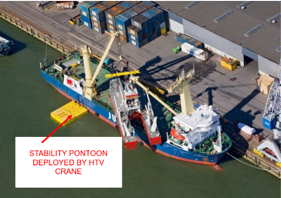
Figure 16: Stability pontoons on an SSCV Credit Heerema)
Disadvantages:
- Time taken to deploy
- Time taken to retrieve
- The stability pontoon is not the full depth of the vessel so only the initial GM is enhanced
- The stability pontoon can only be deployed in very good weather
Advantages
- The geared HTV with the stability pontoon minimises the transport vessel width during transit.
Variable shape for different drafts
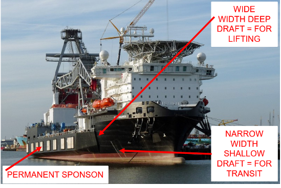
A few mono-hull crane vessels, see Figure 17, use dual draft hull design that creates an optimal combination between a small waterline breadth during transit and a significantly larger waterline breadth with additional stability during heavy lift operations.
Figure 17: Different drafts-different widths (credit Seaway 7)
CONCLUSIONS
The maximum width of an ocean transport vessel is sometimes restricted by the Loadout, ocean tow or installation or when going through a canal. So, temporary stability aids have to be designed in order to meet the minimum stability marine warranty requirements.
Damage can occur from collision or stranding, but incorrect ballasting or uncontrolled flooding are also possible and hence need to be considered.
ACKNOWLEDGEMENTS
Alan Crowle thanks his colleagues at the University of Exeter for their assistance in preparing this article and, in particular, for the assistance of Professor PR Thies.
ABOUT THE AUTHOR

Alan Crowle is a Naval Architect studying for a Masters by Research, at the University of Exeter. The focus of the research is into the load-out, tow out and installation of floating offshore wind turbines.
He has a BSc in naval architecture and shipbuilding from the University of Newcastle upon Tyne (1974) and MSc in engineering for marine professionals at the University of Plymouth (2020). He has over 51 years experience, in the design, construction and offshore installation of marine structures. His work includes jackets, modules, FPSOs, semisubmersibles, loading buoys, LNG terminals and nearshore pipelines. He has renewable energy experience of fixed offshore wind turbines, met masts and high voltage direct current platforms. He is a fellow of RINA, IMAREST and SCMS
