This paper was originally presented in the 27th Offshore Symposium, February 22nd, 2022, Houston, Texas Texas Section of the Society of Naval Architects and Marine Engineers
It has been reproduced here for the readers of TheNavalarch
INTRODUCTION
In 1989 a Class 105 (meaning leg length 105 feet) lifeboat, the AVCO V, capsized with the loss of 10 lives. The Seacor Power was a Class 250 lifeboat with an extra 15 feet added to its legs, making it a Class 265 (meaning leg length 265 feet) vessel. Figure 1 compares the outboard profiles of the 105 and 250 classes.
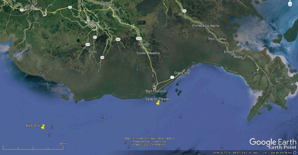
The two capsize incidents occurred about 50 miles apart, off the Louisiana Coast, south of Houma. In the AVCO V capsize [1] the waves were described as “6 and 7 feet” high 30 minutes before the capsize, and building. At the point of capsize, opinions in [1] put the waves as “about 6 to 8 feet high”. The master estimated the seas to be 15 feet high at the point of capsize at 0505 on July 31, 1989. The wind speed was estimated at 30 knots, “gusting to 50 knots”. The water depth at the AVCO V capsize location was 27 feet.
In the Seacor Power capsize [2] the wind speed increased suddenly in a rain squall. Vessels in the area reported winds in excess of 80 knots from the north with rapidly building seas. From testimony given in the August USCG Hearing
[3] less than 30 minutes before the capsize, the wind had been around 18-kt from between south and south-southeast with 3-4 feet seas from the same direction. The vessel was making about 3 knots (from AIS transmission) and heading southeast. In a period of less than 2 minutes the wind changed direction to north (coming from) and its speed was speed registered on the vessel anemometer at 79 mph (67 kt). After about 2 minutes the wind speed dropped (to possibly 40-kt) and a white out occurred (extremely heavy rain and almost zero visibility) for 5-10 minutes. Immediately following the white out the wind speed was noted to be 30-45 mph (26-38 kt) and the waves were estimated to be 3-6 feet, coming from the north and rapidly increasing.
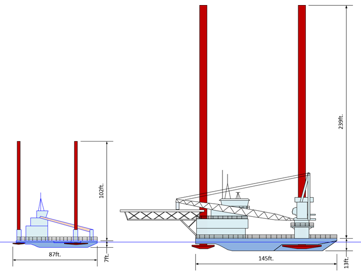
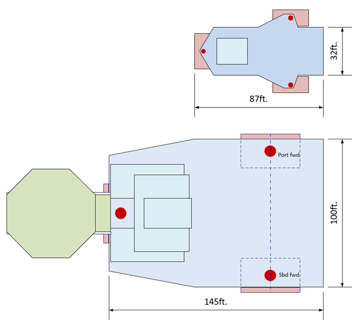
Figure 2 – Plan View Comparisons of the AVCO V and Seacor Power
During the white out the captain decided to stop and elevate the hull. The crew simultaneously began jacking the legs down turning the vessel into the wind. The turn was to port and the capsize occurred to starboard during the turn. The vessel had the wind and waves from the north on its port side at the time of the capsize. The water depth at the Seacor Power capsize location was 54 feet.
From testimony and from AIS transmission during the white out, the vessel speed had been increased by the wind from the north to about 5.0 knots. It is likely to have reduced to less than 4.0 knots during the turn.
TUBE RAFT HULL MODEL – HYDROSTATICS
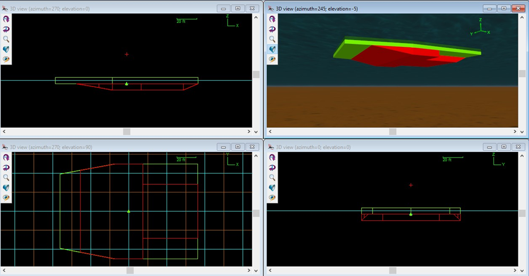
This paper introduces a tube raft. The lifeboat hull is built with a tube raft made from an assembly of OrcaFlex [4] line elements. Each tube has a discrete solution for its buoyancy and Froude-Krylov force. Rafts of tubes are assembled to occupy the same volume as each block of the liftboat hull. Hull geometry blocks are shown in Figure 4.
The target segment length selected for each tube is 7.5 ft. Thus, the longest upper tubes have 19 segments each. The tubes are 6.5 ft OD and very stiff in flexure. All line elements are attached to an OrcaFlex 6D buoy, which represents the vessel hull. Figure 5 shows hull geometry blocks filled with tubes.

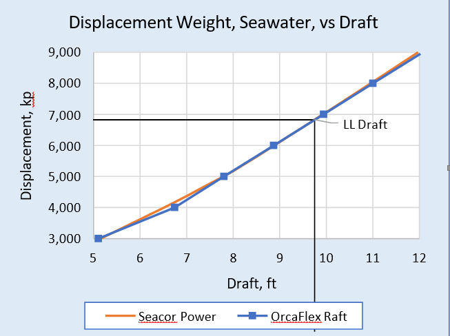
The Seacor Power hydrostatics table from the vessel’s Marine Operations Manual (MOM) was made public in Reference 4. The OrcaFlex tube raft model was adjusted in order to get matching displacement vs draft data to within 0.2% in the operating depth range of interest (from 9 to 10 ft draft). The comparison is shown in Figure 6.
CLASS 250 LIFTBOAT WEIGHT DISTRIBUTION & AFLOAT CONDITION
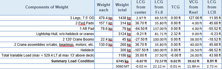
The weight distribution used for the Class 250 liftboat (250-ft leg length) described in this paper is similar to that of the Seacor Power and is shown in Table 1. The Seacor Power had a similar weight distribution but had 265-ft leg lengths and slight differences in its hull, when it capsized.
Table 2 shows the Class 250 tube raft vessel afloat condition, with draft, heel, trim, and allowable KG, based on the Seacor Power allowable KG, as shown in Figure 7.
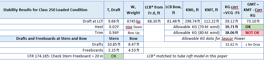
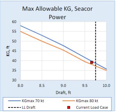
The maximum allowable KG data for the Seacor Power was presented in Reference [3] and is shown plotted in Figure 7 together with the actual draft and KG data for the vessel in this paper, from Table 2.
It was not clear from testimony given in [3] whether the Seacor Power Allowable KG data presented was for the vessel before or after the legs were extended from 250 ft to 265 ft.
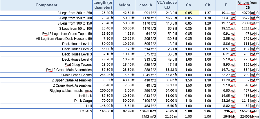
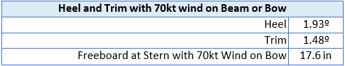
Table 3 presents a summary of wind areas, forces and heeling moments developed for the vessel studied in this paper using the standard industry “building block” method. Selected shape and height coefficients are shown. Results are given for the upright condition for a 9.66-ft draft and 70-kt wind speed.
Separately a large angle heeling moment curve is developed (by rotating the 3-dimensional vessel with zero trim and using projected areas) and applied to find the wind area ratio as discussed later.
LARGE ANGLE STABILITY
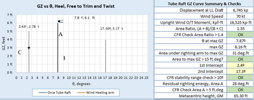
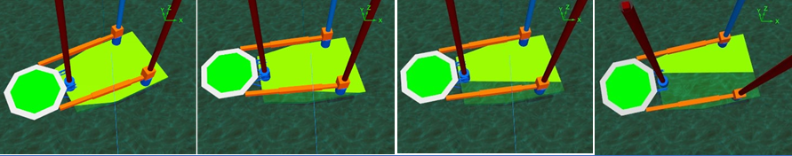
The method used to produce conventional large angle stability data, for tube raft liftboat in this paper, uses OrcaFlex as follows. For free trimming without twist, two pairs of winches are used at fixed elevations, one above and one below the free-floating vessel. The winches are positioned far to each side of the vessel and have long (weightless) winch wires that apply a horizontal pull to points on the vessel above and below the center of flotation. The heeling moment is applied slowly, in the time domain, and very slowly rotates the vessel, which is free to trim and to yaw, or twist, very slightly. No buoyancy of above deck structures is included. The method is illustrated with two annotated screen shots in Figure
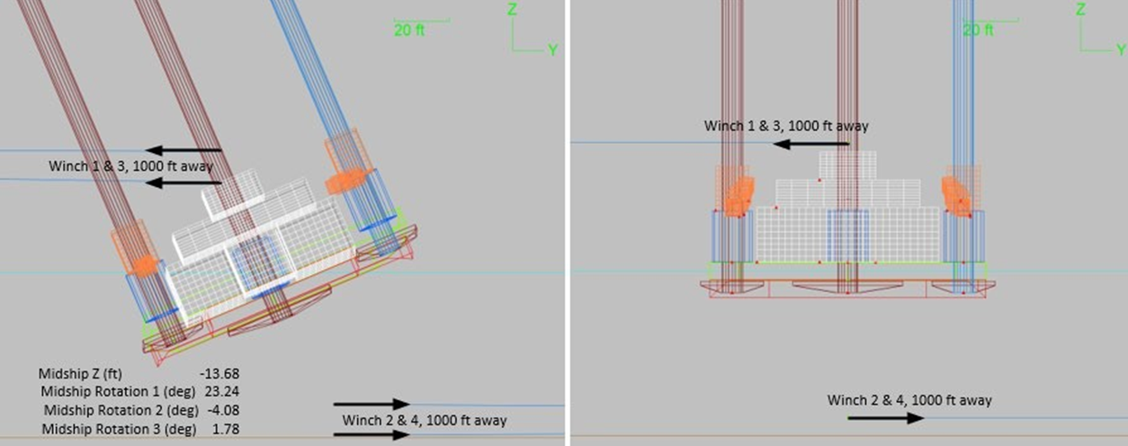
For this paper, the winch loads are increased from zero by steadily reducing the winch wire lengths over a period of 400 seconds. This length of time is sufficient to make inertial effects negligible during the rotation, effectively resulting in a continuous static solution. The adjustment length is set such that the vessel just reaches the limit of positive stability at time equals 400 seconds. Initially simulations are run until the vessel capsizes. The capsize can be observed at real time in the time domain. Just before capsizing, the applied moment from the winches has reduced to zero, the heel angle is 23.4º, the trim is 4.3º (stern down) and the yaw, is 1.9º.
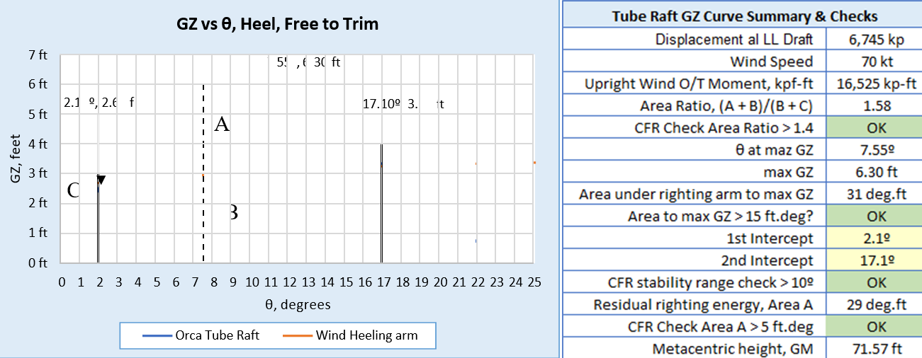
The heeling moment created by the winch loads is divided by the vessel weight to give the righting arm, GZ, which is plotted against the angle of vessel rotation at every time step, to create the GZ curve shown in Figure 9.
The 70-kt wind heeling arm curve is calculated separately and plotted with the GZ curve in the above figure. The resulting area ratio is 1.58, which is 13% above the 1.40 minimum ratio required to satisfy the CFR [5] liftboat stability regulations. The value for θ at maximum GZ is 7.55º and the initial GM is 71.6 feet.
The two-winch moment allows the vessel to twist about the initially vertical axis between the winch wire attachment points (50 ft above and below the vessel midships center). This is similar to the free twist method described by van Santen [6].
It should be noted that the stern deck edge begins to submerge at a heel angle of 2.7º. The bow deck edge begins to submerge at a heel angle of 5.5º, at which point the stern deck edge is submerged by 2.25 feet. At 10º of heel, the stern deck edge is submerged by 7.15 feet and the bow deck edge is submerged by 3.4 feet. The GZ curve is close to linear only up to 4º.
In comparisons of other tube raft hydrostatic models and other large angle stability software, the resulting GZ curves have been found to be accurate to within less than a 2% error.
Figure 12 presents GZ curves for the tube raft trim, in both directions (bow down and stern down) about midship’s axis, starting from the 0.9º stern down condition summarized in Table 2.
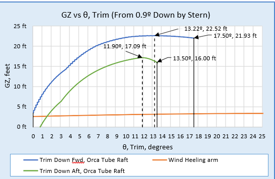
It is important to note that the large angle data this section is presented to give a clear picture of the conventional intact static stability of the liftboat that is subsequently presented with time domain dynamic analysis in waves. The dynamic analysis method, with a tube raft and OrcaFlex, does not use this conventional hydrostatic stability data, in contrast to most widely used seakeeping software. It is also important to note that the GZ heeling curve is linear only up to around 4º of heel angle.
CLASS 250 LIFTBOAT STRUCTURAL MASS MOMENTS OF INERTIA
| Structural Inertia Calculations | Ixx total | Iyy total | Izz total |
| 3 Legs, 7.5′ OD | 68% | 47% | 30% |
| Lightship Hull, inc. pads, helideck, crane booms | 25% | 28% | 63% |
| 2 Crane assemblies w/cabs, bearimgs, motors, etc. | 3% | 2% | 0% |
| Helideck | 1% | 16% | 2% |
| Total Variable Load (max = 529.4 LT at max 13′ above deck) | 2% | 8% | 5% |
| Totals (kp.ft^2) | 1.35E+07 | 2.28E+07 | 1.47E+07 |
The mass moments of inertia for the vessel in this paper are summarized in Table 5. These data are attached to the Orcaflex 6D buoy located at the cg of the tube raft model.
HYDRODYNAMIC ADDED MASS AND ADDED MOMENTS OF INERTIA
Fixed frequency terms for added mass and inertia for the tube raft heave, roll and pitch freedoms are shown in Table 6.
| Hydrodynamic Mass in heave | 21,200 kp |
| Hydrodynamic Inertia in roll | 1.19E+07 kip.ft^2 |
| Hydrodynamic Inertia in pitch | 5.70E+07 kip.ft^2 |
The hydrodynamic mass and inertia terms are selected from the in-house version of the author’s program STA BARMOT. This is a barge motions program used for calculating displacement RAOs, partly based on model test data and partly based on diffraction and Froude-Krylov calculations.
NATURAL PERIODS AND MOTION DECAY IN STILL WATER
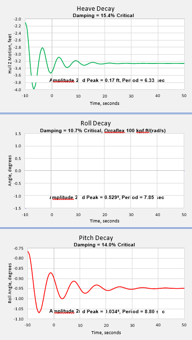
Figure 13 shows decay curves of small amplitude pitch, roll and heave motions of the OrcaFlex tube raft vessel in still water, 60 feet deep. The natural periods of pitch, roll and heave are estimated from the decay curves and shown in Table 7.
The restoring forces are not discretely input but are a result of the combined forces at each time step, on each segment of each tube, or OrcaFlex line element, in the theoretically undisturbed wave.
The constant hydrodynamic damping terms for the OrcaFlex tube raft (applied at a point close to the center of buoyancy in still water at an even keel) are adjusted from experience to obtain the expected form of decay for the liftboat vessel. The damping forces and moments selected are directly proportional to the velocity or angular velocity of the vessel relative to earth, to simulate radiation damping, see Reference [4] for more details. The selected hydrodynamic damping terms are shown in Table 7.
| Characteristic | Heave | Roll | Pitch |
| Natural Period | 6.38 sec | 7.82 sec | 8.73 sec |
| Hydrodynamic Damping | 250 kpf/(ft/s) | 1.00E+05 kpf.ft/(rad/s) | 4.00E+05 kpf.ft/(rad/s) |
| Equivalent %age Critical Damping | 15.40% | 10.70% | 14.00% |
The natural periods of the moored vessel, for response in waves, are also found from OrcaFlex modal analysis and are shown in Table 8, below.
| Characteristic | Surge | Sway | Yaw |
| Natural Period | 81.68 sec | 81.64 sec | 24.66 sec |
| Characteristic | Heave | Roll | Pitch |
| Natural Period | 6.22 sec | 7.73 sec | 8.66 sec |
RESPONSE TO 1-FT REGULAR WAVES IN 60-FT WATER DEPTH
The RAO definition used for the following charts is the response range divided by the wave height, noting that the response and the wave may both be non-sinusoidal, but periodic, and may both be about non-zero mean values. As will be shown later, the periodic responses of roll and pitch may be at twice the wave period, or subharmonic.
Heave, roll and pitch response results from time domain analyses in regular stream function (10th order) 1-ft high waves at attack angles 0º (from the stern), 45º and 90º are summarized in Figure 14. The model is held in 60-ft water depth, on a 4-line mooring with one attachment point at the centerline on the bow and one on the stern. Long light horizontal lines at ±45º from each end of the vessel are used.
The load condition shown in Table 2 is used, with an initial 0.94º of stern down trim. The vessel is analyzed with zero forward speed. The following RAO chart axes are kept the same for each response type (heave, roll, pitch) for each wave attack angle, thereby enabling easier comparison of values with different wave heights.
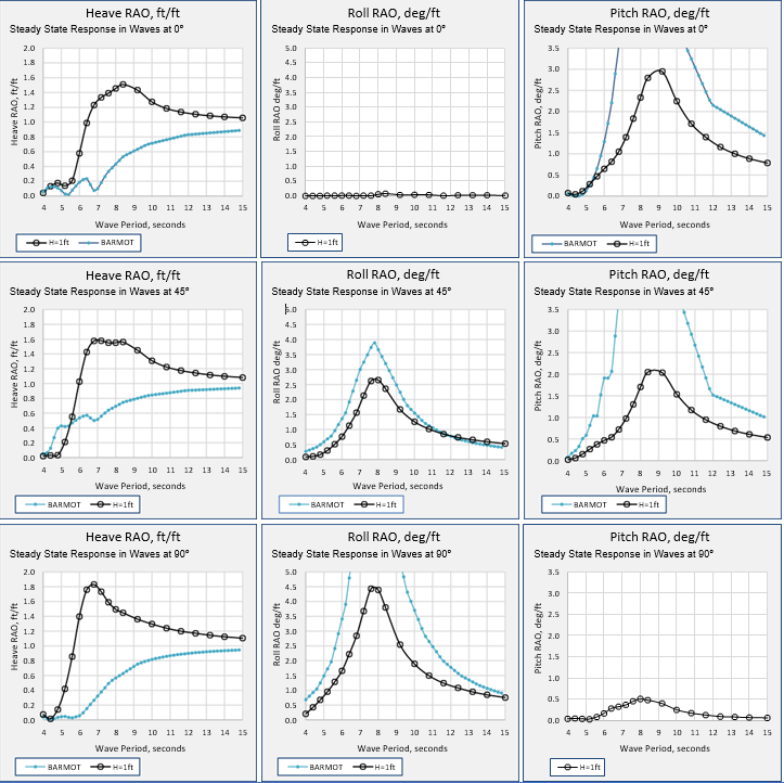
The steady state response ranges (plotted as RAOs) in 1-ft waves, for heave, roll and pitch for the OrcaFlex tube raft, are shown for wave attack angles of 0º, 45º and 90º in Figure 14. Results from STA BARMOT are shown for comparison, but it must be noted that the Class 250 vessel dimensions, with L/B = 1.44 and B/T = beam/draft = 10.4, are well outside the range for which the program has been calibrated.
Each segment of each tube in the tube raft experiences hydrostatic and hydrodynamic forces in waves. The standard OrcaFlex Morison equation is used with drag force coefficient, Cd, set to zero or 0.1 and the added mass coefficient, Ca, set to zero. The inertia coefficient, Cm is set to the default value of 1.0 in the normal directions, thus giving the
Froude-Krylov pressure force on each tube. The added mass terms for the tube raft are separately specified as described in a previous section. Diffraction forces are not calculated.
For the 1-ft waves and the 0º wave direction, the heave RAO reaches a peak value of 1.5 (ft/ft) at 8.4 seconds then decreases towards 1.0 at 15 seconds. The BARMOT values underestimate the heave peak (close to the pitch natural period). For 1-ft waves and the 90º direction the heave RAO reaches a peak value of 1.8 at 6.8 seconds (the heave natural period) and then decreases towards 1.0 at 15 seconds.
For 1-ft waves at 0º the pitch RAO peaks at 2.9 (deg/ft) at 8.7 seconds, the pitch natural period. For 1-ft waves at 90º the roll RAO peaks at 4.5 (deg/ft) at 7.7 seconds, the roll natural period. BARMOT predicts similar RAO behavior with lower amplitudes.
RAOS FROM RESPONSES TO REGULAR WAVE UP TO 9-FT IN 60-FT WATER DEPTH
In larger waves the form of the displacement RAOs change significantly, as the liftboat deck edges become submerged and the restoring forces become far from linear. Additionally, the response in stern seas and head seas are notedly different, partly due to the above and below water hull shape and partly due to the trim angle
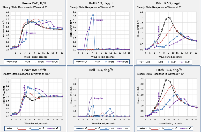
Figure 15 presents a comparison of tube raft RAOs in stern (0º) and head (180º) seas with 1-ft, 3-ft, 6-ft, and 9-ft wave heights. In head seas (180º) the heave RAO for 1-ft waves peaks at 1.1 (ft/ft) at 7.0 seconds, then decreases to 0.8 at
8.5 seconds, then rises to just over 1.0 and stays at this value from 11 to 15 seconds. In stern seas the RAO for 1-ft waves, as described previously, peaks at 1.7 at 8.4 seconds then decreases towards 1.0 at 15 seconds.
The heave RAOs generated from responses to waves larger than 1-ft have similar values up to around 7 seconds and then have peak values occurring at longer periods. Peak values are all around 1.6 for stern seas.
The pitch RAOs for 1-ft waves are similar for beam and head seas, both peaking around 8.7 seconds, with head seas having a slightly larger value of 3.3 (deg/ft). The pitch RAOs generated from higher waves show decreasing peak values at progressively longer periods, all decreasing to a value of 0.8 at 15 seconds.
The vessel capsizes in 9-ft regular waves in both stern and head seas. Capsize occurs in both seas with periods from
- to 8.4 seconds. The data point at the last period before capsizing is marked on the charts with the word capsize. The response curve is continued at the next period for which a steady state response is found, until 15 seconds wave period. Significant submergence of the deck is seen in the capsize cases.
Surge sway and yaw motions are computed but detailed responses are not reported in this paper. The yaw motions, restrained by the mooring system, keep the selected vessel heading from deviating by more than ±4º in up to 6-ft waves, and to within ±8º in 9-ft waves.
Some of the differences in the RAO curves generated with different wave heights are attributed to the increased influence of the water depth on the hydrodynamic characteristics of the wave as height increases (as predicted by the 10th order stream function theory being used in this paper). Larger differences are attributed to the non-linear hydrostatic restoring forces as increasingly larger parts of the deck become submerged during the steady state responses observed.
The unexpectedly large roll response in stern and head seas, with 6-ft and 9-ft wave heights, at periods from 5 to 8 seconds is discussed later
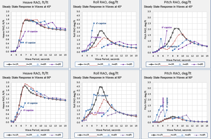
Figure 16 shows that the vessel capsizes in 6-ft and 9-ft regular waves from 45º and 90º. The maximum period range for capsize is from 6.4 to 8.4 seconds. The heave RAOs for beam waves (90º) generated from responses to waves larger than 1-ft, have similar values to the 1-ft wave heave RAO. The roll RAOs for 45º and 90º directions, for 3-ft, 6-ft, and 9-ft waves, show similar & 180characteristics to the pitch RAOs for larger waves in the 0º direction, with peak values occurring at longer periods at the wave height increases.
The heave RAOs for beam waves (90º) generated from responses to waves larger than 1-ft, have similar values to the 1-ft wave heave RAO. The roll RAOs for 45º and 90º directions, for 3-ft, 6-ft, and 9-ft waves, show similar &
180characteristics to the pitch RAOs for larger waves in the 0º direction, with peak values occurring at longer periods at the wave height increases.
MAX RESPONSES, NO WIND, 1-FT TO 9-FT WAVES, 0º & 180º, 60-FT WATER DEPTH
In this section the vessel maximum heave, roll and pitch steady state responses are presented (not RAOs, as in the previous section) to regular waves with heights 1-ft, 3-ft, 6-ft, and 9-ft, from directions 0º, and 180º. The results are summarized in Figure 17, below.
The data point at the last period before capsizing is marked on the charts with the word capsize. The response curve is continued at the next period for which a steady state response is found, until 15 seconds wave period. Significant submergence of the deck is seen in the capsize cases
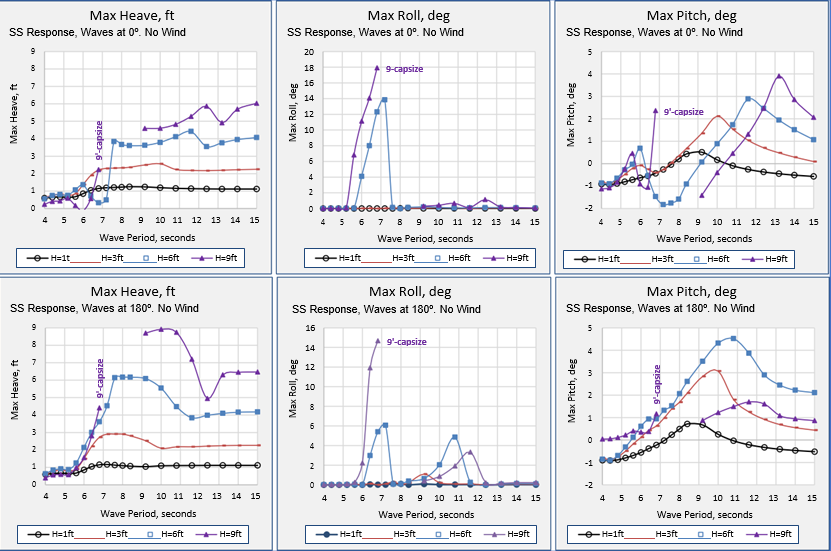
In 6-ft and 9-ft waves, for both wave directions, a large amplitude steady state roll response becomes periodic at exactly twice the wave period, in the wave period range leading up to the roll natural period of 7.8 seconds. In some cases, the pitch response also “locks” into this twice-wave-period response.
Figure 18 illustrates a condition where the roll response (red curve) is at twice the wave (dark red) period with the pitch (blue curve) remaining the same as the wave period. The wave direction is 0º and the wave height is 6-ft.
In 1-ft and 3-ft waves, the roll response is periodic at the wave period in all cases and no twice-wave-period responses are found.
In these stern and head seas, the unexpectedly large roll, has similarities with parametric rolling of large ships which is well described by the ABS in [7].
PARAMETRIC ROLL RESONANCE IN LONGITUDINAL WAVES
In parametric roll resonance, when a ship moves in longitudinal waves, the roll response is periodic at, or close to, the ship’s natural roll period. It is caused by the periodic change of stability as the roll restoring moment is increased and decreased during the passage of a wave. An increase in the waterplane area occurs when wave crests are simultaneously passing the flared parts of the bow and stern, and the wave trough is at midships. A decrease in the waterplane area occurs when the wave crest is at midships [7].
The large amplitude, twice-wave-period roll, and pitch response of the Class 250 liftboat described in this paper is not considered to be associated with these same changes of the waterplane area (and hence changes in roll stiffness) during the passage of waves in the longitudinal direction.
In most large amplitude roll responses in stern and head waves, the liftboat pitch motion begins with a response that locks into the twice-wave-period mode and roll is negligibly small. The pitching amplitude then reduces, and its response period becomes the same as the wave, while the roll amplitude becomes large and sub-harmonic, at twice the wave period. These twice-the- wave sub-harmonic periods are longer than the roll and pitch natural periods in still water.
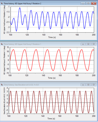
In Figure 19 the wave elevation is shown in dark brown and has a period of
6.8 seconds. The blue pitch response initially builds to +4º to -7º (representing an amplitude of 5º about a mean of -1º, which is the vessel initial trim) and has a period of 13.6 seconds. The pitch then decays to around 1º amplitude with a period of 6.8 seconds. The red roll response begins with negligible amplitude and grows to an 8º amplitude at twice the wave period as the pitch reduces.
In 8 seconds and longer period waves, the heave, roll and pitch responses all quickly reach a steady state at the wave period. In longitudinal seas, roll is close to zero, as expected.
Exceptions where small amplitude roll motion is seen at longer periods in head seas are associated with small mean angles of yaw (between 1º and 3º) permitted by the mooring system. The roll response is at wave period in these cases.
Capsize occurs in 9-ft regular waves from both the 0º and 180º directions. Capsize does not occur in these directions with 6-ft waves.
The phenomenon of sub-harmonic (period-doubling) motion of other ocean structures (not free floating) has been reported elsewhere and confirmed with model tests [8].
MAX RESPONSES, NO WIND, 1-FT TO 9-FT WAVES, 45º & 90º, 60-FT WATER DEPTH
In this section the vessel maximum heave, roll and pitch steady state responses are presented to regular waves with heights 1-ft, 3-ft, 6-ft, and 9-ft, from directions 45º, and 90º. The results are summarized in Figure 21, below.
Capsize occurs in both 6-ft and 9-ft waves from 45º and 90º.
In wave periods less than the roll and pitch natural periods, both roll and pitch show large amplitude periodic responses at twice the wave period. The roll and pitch response period ratios are presented for all steady state responses from time domain simulations in Table 9. This table also summarizes all conditions where capsize occurs.
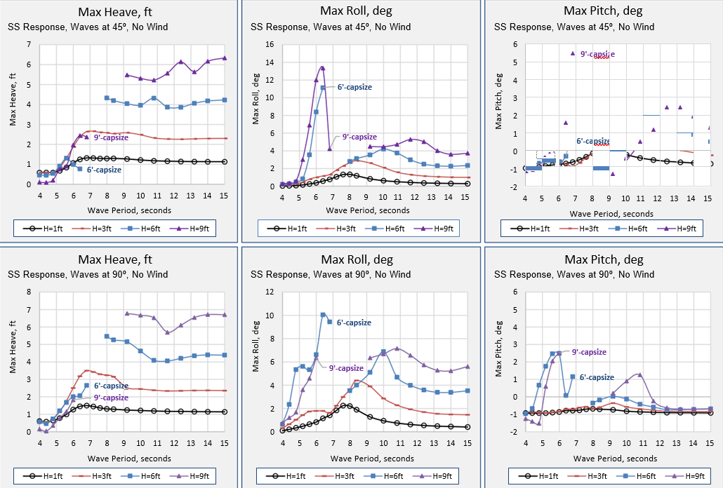
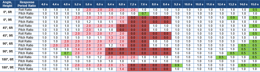
Table 9 is arranged with wave periods in the top row and wave direction and height in the left column.
- Cells with a light red color indicate roll or pitch steady state response period ratios of greater than 1.3. Values of 2.0 indicate response at twice the wave period.
- Cells with dark red color indicate capsize.
- Cells with green color indicate response period ratios of less than 0.9.
No results are included for 1-ft and 3-ft waves where all responses were found to be at the wave period, as expected, and no capsize was found.
MAX RESPONSES, REGULAR WAVES WITH 50-KT & 70-KT WIND HEELING
Time domain steady state responses for all runs in waves without wind were repeated with wind heeling moments from 50-kt wind and 70-kt wind. The heeling moments were applied as a constant local moment and did not have any variation with roll angle or wave direction. The moment was applied as if the wind was always coming from the 90º direction. Results are summarized in Figure 22 and Figure 23.
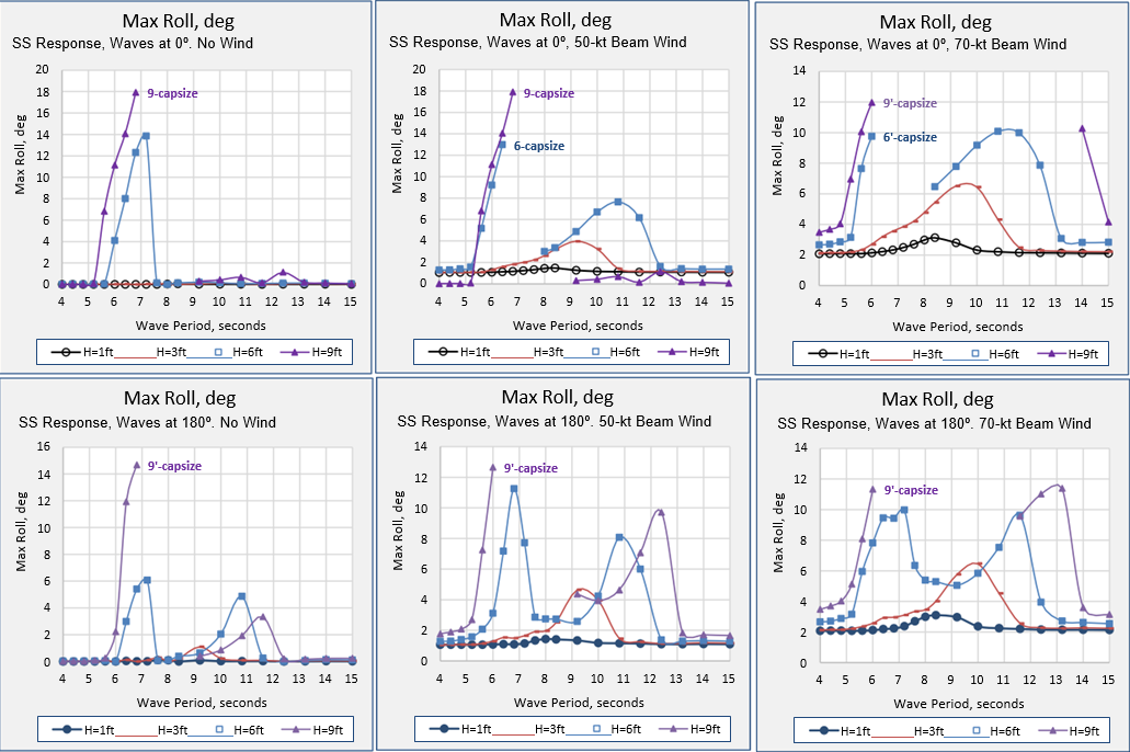
Figure 22 shows capsize occurs in stern seas in both 6-ft and 9-ft waves with 50-kt and 70-kt beam winds. Capsize occurs in head seas, only in 9-ft waves with 50-kt and 70-kt beam winds. The range of wave periods with capsize is increased up to 13.2 seconds in stern seas with 70-kt beam winds.
Figure 23 shows capsize in both 6-ft and 9-ft waves at 45º and 90º, with and without beam winds. The range of wave periods with capsize with 9-ft waves and 70-kt beam winds is increased up to 13.2 seconds with waves from 45º and up to 10.8 seconds with beam waves.
Note that all results are without forward speed and without any rudder or other turning forces. Class 250 liftboats rarely travel at more than 5 knots in still water and reduce speed in waves.
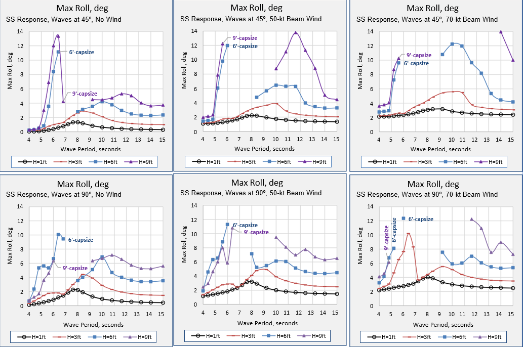
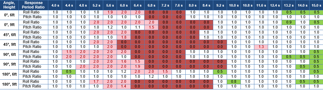

Table 10 and Table 11 have the same format and arrangement as Table 9 with wave periods in the top row and wave direction and height in the left column. The dark red cells indicate conditions with capsize.
INFLUENCE OF ROLL DAMPING
Limited investigations into the effects of significantly increased or decreased roll damping were undertaken. With hydrodynamic damping (proportional to the vessel angular velocity relative to earth) significantly increased (to above an equivalent of 20% critical) the change from large amplitude sub-harmonic pitching to large amplitude sub-harmonic rolling in longitudinal waves is reduced or does not occur at all. With this very large damping, capsize is not found in 6-ft waves and 70-kt wind, but still occurs in 9-ft waves and 70-kt wind.
With roll damping reduced to an equivalent of around 5% critical, the roll amplitudes are increased and capsize is found in 6-ft waves where it did not occur with 10% critical damping. The sub-harmonic roll response remained common to 6-ft and 9-ft waves but did not occur in 1-ft or 3-ft waves.
CAPSIZE IN IRREGULAR WAVES
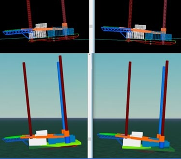
Capsize is found in irregular waves with 5-ft to 6-ft significant wave heights, with and without wind heeling forces. A full description is beyond the scope of this paper. Figure 24 provides a visual example of a capsize sequence in a JONSWAP following sea with Hs = 6-ft, Tz = 6 sec and γ =2.0, with a 50-kt wind on the starboard side, causing heeling to port. The port leg is colored blue. Twelve screen captures are shown each taken one second apart. Each capture shows a side elevation, an end elevation and a plan view with shaded graphics and perspective.
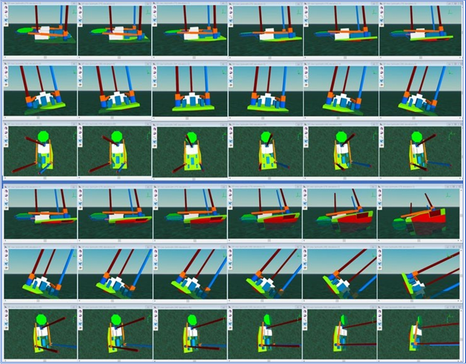
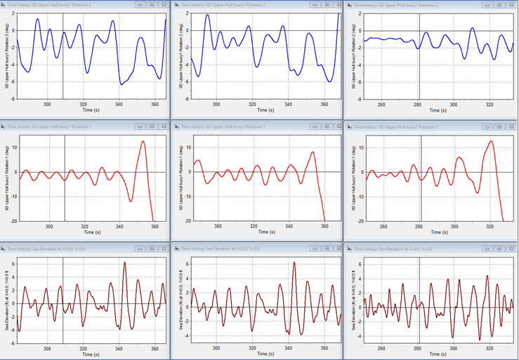
Figure 25 shows three sets of time histories for pitch, roll and wave elevation (blue, red, and brown) for three cases with a 50-kt wind all resulting in capsize. The cases are for wave attack directions of 0º, 45º and 90º (left, middle and right) with a JONSWAP wave spectrum of long-crested waves with Hs = 6-ft, Tz = 6 sec and γ = 2.0. The charts are drawn with the same vertical scales for each color. The red roll negative axis is limited to 20º to show more clearly the roll response in the 80 seconds before the capsize.
The capsize sequences in waves from 0º and 45º both begin during the passage of a relatively high wave with a 4-ft trough, 6.3-ft crest, and 6.9 second period from trough-to-trough. In both these cases the response before and during the capsize shows pitching with a longer period than the waves.
The capsize in 90º waves is not associated with a single high wave event but is preceded by a 20-second build-up of longer-than-wave-period pitching and rolling. The capsizes are not associated with a “Pure Loss of Stability” as defined by the IMO and which is a common reason for fishing vessel capsize on the crest of a wave [9].
No vulnerability criteria for capsize appropriate to vessels like liftboats appears in drafts of the IMO Second Generation Intact Stability Code [10] although the Dead Ship Condition, which applies to vessels in beam seas, suggests model tests.
INFLUENCE OF LEG LOWERING
A little over one minute before the capsize, the Seacor Power had begun lowering her legs at a rate of 6ft/minute. As the buoyant 7.5-ft OD legs and 40-ft x 23-ft pads lowered from beneath the upper hull, the heave, roll and pitch damping would have been increasing, and the vertical centers of gravity and of buoyancy would have been lowering. The pad of one leg can be seen lowered by about 10 feet in photos of the capsized vessel. The combined effect of lowering the legs by 10 feet would have been to slightly reduce the likelihood of capsize.
EFFECT OF BUOYANT SUPERSTRUCTURE
Responses change significantly when the tube raft elements are extended above the barge deck to model the weathertight deck houses. Capsize nevertheless occurs. Full results are beyond the scope of this paper.
MODEL TESTING
A well-planned series of model tests is advocated to investigate the dynamic afloat stability of liftboat-type hulls, with relatively low freeboard/beam and draft/beam ratios and relatively high centers of gravity, partly as a result of their long legs. The author originally proposed such a series of tests when he chaired the SNAME Liftboat Committee over 20 years ago.
SUMMARY AND CONCLUSIONS
- Liftboats have wide beams, shallow drafts, and low freeboards. They experience water on deck and deck edge submergence in relative low wave heights. This makes them difficult to model with most seakeeping software.
- Two cases of intact liftboat capsize in waves with loss of life highlight the need to provide better guidance for liftboat capsize avoidance in waves.
- The Class 250 liftboat, in the nearly full load condition as presented in this paper, is prone to capsize in 6-ft waves from the beam and quartering directions, without any wind.
- It is shown how a liftboat vessel hull can be modelled as a tube raft built from an assembly of general purpose OrcaFlex line elements.
- The tube raft model is shown to have accurate large angle stability properties in still water.
- The model permits unlimited submergence at any angle in a time domain analysis while reliably predicting hydrostatic restoring forces.
- The model is demonstrated to have natural heave, roll, and pitch natural decay curves in still water with the expected natural frequency and damping properties of the liftboat vessel.
- Dynamic response to non-linear steam function (and other) waves can be simulated in shallow water, although the presence of the vessel does not alter the wave particle kinematics.
- The model includes Froude-Krylov forces within the whole of the wetted surface (entire volume) and constant hydrodynamic added mass terms for 6DOF. Diffraction forces are not included.
- Time domain analysis of the model demonstrates that vessel RAOs change their form with increasing wave height and are not linear with wave height.
- The model illustrates deck submergence (or deck in water) in waves, but the solutions are of unknown accuracy.
- The model is able to realistically simulate capsize and identify wind and wave conditions that will result in capsize.
- The time domain simulations run relatively quickly, with a batch of twenty 10-minute real time analyses taking 5 minutes computer time.
- Large amplitude sub-harmonic rolling, and pitching are observed at twice the wave period for periods leading up to roll and pitch natural periods in still water. This motion has similarities with but is not the same as parametric rolling.
- Model tests are needed to define limiting metocean conditions more reliably for safe transit of liftboats.
REFERENCES
- NTSB, Marine Accident Report, Capsizing and Sinking of the U.S. Liftboat M/V AVCO V, Gulf of Mexico,
July 31, 1989
- NTSB, Preliminary Report, Marine, DCA21MM024, Capsizing and Sinking of the US-flagged Liftboat Seacor Power, April 13, 2021.
- USCG Marine Board Hearing, Capsizing and Loss of Life on the Seacor Power, April 13, 2021, USCG and NTSB Joint Formal Public Hearing and Examination, Houma, LA, August 2 – 13, 2021.
- OrcaFlex, Finite Element Computer Software for Static and Dynamic Analysis of Ocean Structures, Developed by Orcina Ltd., UK.
- US Code of Federal Regulations, Title 46 / Chapter I / Subchapter S / Part 174 / Subpart H – Special Rules Pertaining to Liftboats, Source: CGD 82-004 and CGD 86-074, 62 FR 49355, Sept. 19, 1997.
- Santen, JA van, Problems met in stability calculations of offshore rigs and how to deal with them, 13th International Ship Stability Workshop, 2013.
- ABS GUIDE FOR THE ASSESSMENT OF PARAMETRIC ROLL RESONANCE IN THE DESIGN OF CONTAINER CARRIERS, 2019.
- Orszaghova J, Wolgamot H, Draper S, Eatock Taylor R, Taylor PH, Rafiee A. Transverse motion instability of a submerged moored buoy. Proc. R. Soc. A 475:20180459, 2019.
- Matsuda, A., Terada, D., Hashimoto, H., The characteristics of capsizing phenomena of Japanese fishing vessels, Proceedings of ISSW 2017.
- Naval Surface Warfare Center, Carderock Division, Development of Second Generation Intact Stability Criteria, NSWCCD-50-TR-20011/065, December 2011.
Author’s Profile

Founder and CEO at Stewart Technology Associates
Bil has over 40 years of professional civil, structural and offshore engineering experience.
He has published over 35 technical papers and has authored many hundreds of reports dealing with a wide variety of ocean structures. He has been active with many professional societies and was chairman of the Offshore committee for SNAME, served on the OTC Program Committee, the National Offshore Safety Advisory Committee, various API and ASME committees, was a Technical Editor for SPE, and is currently Chairman of the ASCE COPRI Marine Renewable Energy Committee, President-elect COPRI 2017. He became a Chartered Engineer in Europe in 1977 and a Professional Engineer in Texas in 1983.
Specialties: Specialized in the design and analysis of dynamically responsive fixed and floating structures in the marine environment. Clients have included most major oil companies, drilling contractors, engineering companies, banks and investment companies, the US Navy, the US Coast Guard, the US Air Force, defense contractors, insurance companies and warranty surveyors, lawyers and manufacturers.
Part-time lecturer in dynamics of offshore structures, with emphasis on analysis with OrcaFlex, at Texas A&M University, Galveston.

Thanks to TheNavalArch for re-printing the paper.
It is emphasized that this liftboat is predicted to capsize in 6-ft waves WITHOUT wind.
Kind regards, Bil
Very informative read on the capsize of a liftboat during transit. Well done!
all about Ship