Cathodic protection of a structure is an exercise which requires close study of the structure on which it is going to be implemented. The type and quantity of cathodic protection by anodes will depend upon multiple factors: the Geometry of the Structure, the environment of the Structure, and its special design needs. In this article we examine in some more detail the differences in approach to Cathodic Protection Design of three different types of offshore structures: 1. Offshore structures and Ships 2. FPSO’s 3. Subsea Pipelines
This article is based on the following references:
- For offshore structures/Ships: DNV-RP-B-401
- For FPSO’s: DNV-RP-B-101
- For Subsea Pipelines: DNV-RP-F-103
First, let’s talk about the structures themselves. Conventional ships are merchant and passenger vessels, like tankers, bulk carriers, general cargo vessels, container ships, cruise liners, tugs, fishing vessels or any other such commercial ships which undertake voyages from one point to other. Offshore structures are permanently installed platforms for production of oil/gas.
FPSO’s are specialised ships which are used for Oil production, storage and offloading (Floating Production, Storage and Offloading). They are stationed at a location for several years which oil is being produced.
Subsea pipelines are meant to carry fluids, and they can be non-submerged, partially-submerged or fully submerged in the sea bed.
Let’s now examine how the different factors lead to different approaches for cathodic protection design of these structures:
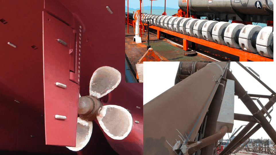
- Geometry of the structure – a typical ship shaped structure can be protected mostly by flat/rectangular anode types (flush mounted, slender type). However, a pipeline, being circular in section, may not be effectively protected by flat anodes and will require bracelet type anodes which can embrace themselves around the pipeline’s circumference. Shown below are some commonly used geometries of anodes.
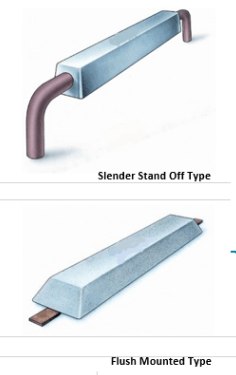
Flat Anodes – for ship hulls,internal tanks and other relatively flat structures
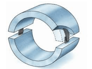
Bracelet Anodes – used for subsea pipelines
- Location and environment of the structure – Temperature, salinity and water depth of the environment are the major factors which influence corrosion. Conventional ships operate in a seawater environment with salinity/temperature being influenced by their zone of operation. FPSOs and subsea pipelines are tied to their environment for whole of their lives which run into several years.
- Temperature: The rate of corrosion is highly affected by the ambient temperature of the metal surface. The current demand of structures which are in tropical regions varies significantly from those in temperate or arctic regions, as demonstrated by the tables below from DNV-RP-B-401 & DNV-RP-B-101. For subsea pipelines, since the metal surface is not directly exposed to the seawater (pipelines being concrete coated), it is the internal fluid temperature and not the seawater temperature that is the governing factor. The same is demonstrated from the table below from DNV-RP-F-103. Temperature also affects the properties of the anode itself. The resistivity of the anode varies with temperature and salinity of the sea environment, as demonstrated from the graph below.
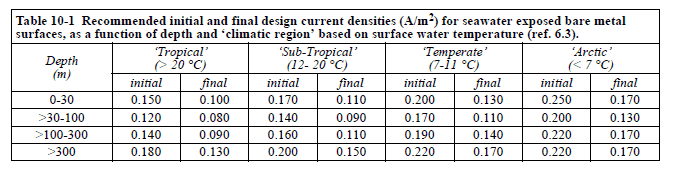
Table 1: DNV-B-401-Current-Densities for different Temperature and Water Depth
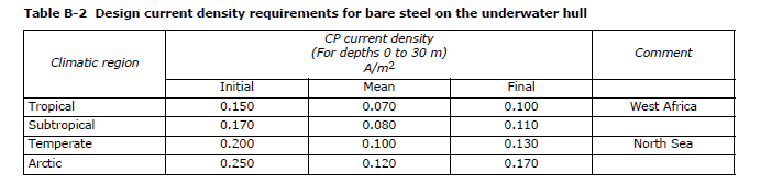
Table 2: DNV-B-101-Current-Densities for different Temperature and Water Depth for FPSO’s
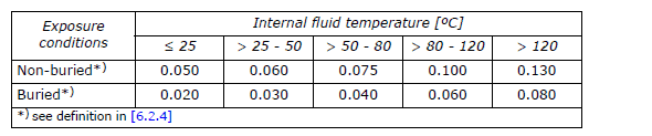
Table 3: DNV-F-103-Current-Densities for different fluid Temperatures for Pipelines
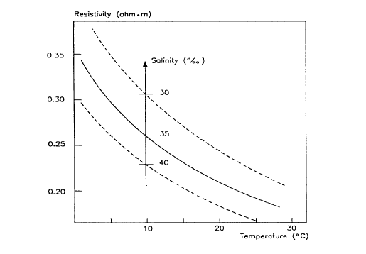
Fig 1 Resistivity vs Temperature and Salinity
-
- Salinity: The salinity of the environment also affects the corrosion protection design, as it directly impacts the resistivity of the anode (see above graph). A higher salinity at low temperatures leads to high resistivity of the anode. This results in low current output of the anode, thus leading to more number of anodes needed. For buried anodes, DNV-RP-B-401 recommends that the resistivity be multiplied by a factor of 2 to 5 (Sec 6.7, DNV-RP-B401). However, DNV-RP-F103 (Sec 6.5.2, for pipelines) recommends that an actual measure of soil resistivity be provided for buried anodes. It is expected that for buried anodes (mostly for pipelines or for vessels operating in sediment-rich water) the resistivity will be much higher compared to anodes in sea water (conventional ships and FPSO’s), thus leading to higher demand for anodes.
- Coating system on the structure
- The coating method applied for the structure also affects the demand for anodes. If the structure is protected by strong protective coating, then the current demand on anodes is less. However, if the structure is not protected by coatings or protected by thin coatings, the current demand will be significantly high. This is accounted for by a factor called coating breakdown factor. It is a fraction which is multiplied to the current demand of the surface to arrive at the actual required current demand. For more details on coating breakdown factor, please refer to our other article Cathodic Protection of Ships. For ships, depending on the thickness/layers of coating applied, the breakdown factors vary (see Table 4 below). For FPSO’s generally the coating category III is followed, and the factors are taken from Table 5. For pipelines, the coatings may vary widely and it is important to select the right breakdown factor depending on the type of coating. This is shown in Table 6.
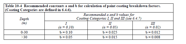
Table 4 DNV-B-401-Coating-Breakdown-Factors for ships
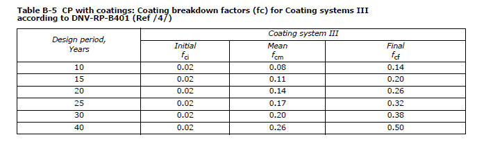
Table 5 DNV-B-101-Coating-Breakdown-Factors for FPSOs
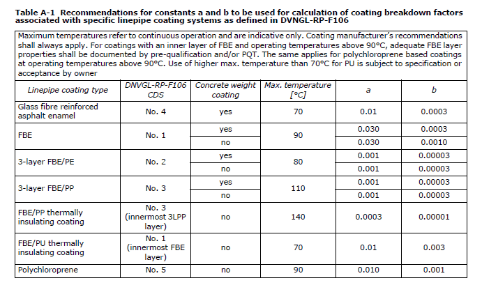
Table 6 DNV-F-103-Coating-Breakdown-Factors for subsea pipelines
- Other differences
- In FPSO’s, the design current density requirements for Tanks is different from that of external hull, as shown in the Table 7 below.
- The salinity for subsea pipelines in brackish water may vary over a much higher range (down to as low as 5%) compared to Ships/Platforms/FPSO’s which generally operate in deeper open ocean. See Fig 2 below
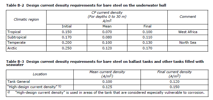
Table 7 DNV-B-101-Current-Density-Tanks-vs-Hull-FPSO
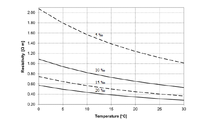
Fig 2 DNV-RP-F103 Resistivity vs Salinity for low salinity areas
Thus, we see that there are significant differences in the approaches for Cathodic protection design for different structures, and same method can’t be applied to all. It is important to take into account these differences to arrive at a solution which is suitable for the structure under consideration.
Please do remember to checkout the few products from TheNavalArch below. These are helpful in cathodic protection design of Ships/Offshore Structures and FPSO’s. The Cathodic Protection Design App for pipelines is due to be launched soon.

Good morning
We are looking for technical assistance in the field of cathodic protection in the sea sector for a project in Algeria.
please contact us at this email address z.neggaz@technorepair-dz.com
report