In this two part article we will talk about Fendering, which is one of the basic but critical operations related to a ship. Fendering is, basically, protecting the ship’s sides from contact with another body (which can be another ship, jetty or quay wall). It can also mean protecting the jetty or berth from contact with ships. Thus, there are two situations for which fenders may need to be designed:
- For Ship-to-Jetty berthing
- For Ship-to-Ship berthing
This is a two part article. In this first part, we will cover the following:
- Berthing Energy
- Berthing types – side and end berthing
- Selecting the right fender
- Rules and standards
The second part will cover the detailed engineering calculation of Berthing Energy.
Section A: Berthing Energy
When a ship comes close to the berth or close to another ship, then there is a chance of the ship’s body impacting against the berth or other ship. This impact can damage the ship’s body or the berth. Fenders are provided to absorb the impact of berthing, and minimize the effect on the ship or berth/jetty.
If there is no fender, this energy KE (the Berthing Energy) will be completely transferred to the Jetty OR the other Ship.
Thus a fender is meant to absorb the impact during berthing. The energy of impact is called the ‘Berthing Energy’
We will now discuss the mechanics of impact, and what is the berthing energy which the fender has to absorb.
When a body moves, it carries with it the kinetic energy of motion. During an impact, the kinetic energy is transferred to the body impacted. The kinetic energy is given by
Kinetic Energy of Impact, KE = ½ x M x V2
There are two scenarios possible
- Ship (say, Ship 1) berthing along a Jetty or Quay
- Ship (say, Ship 1) berthing along another Ship (say, Ship 2)
Mass, M
In case of a ship berthing along a Jetty or Quay, M is the mass of the Ship 1. In case of Ship 1 berthing along Ship 2, M is the ‘effective mass’ of the two-ship system. The Ship 1 moves relative to the ship 2 as a body of mass
M = M1 x M2/ (M1 + M2),
where M1 = mass of Ship 1, M2 = mass of Ship 2
Berthing Velocity
The velocity of berthing, V, is a very critical input in calculating the berthing energy. The berthing velocity is determined based on many factors
- Ship size to be berthed.
- Environmental parameters at location of berthing – whether berthing is sheltered or exposed
- Berthing angle and ease of berthing
A guide for determining the berthing velocity is found in PIANC 2002. A graph which shows different curves considering different berthing scenarios is used to determine the berthing velocity.
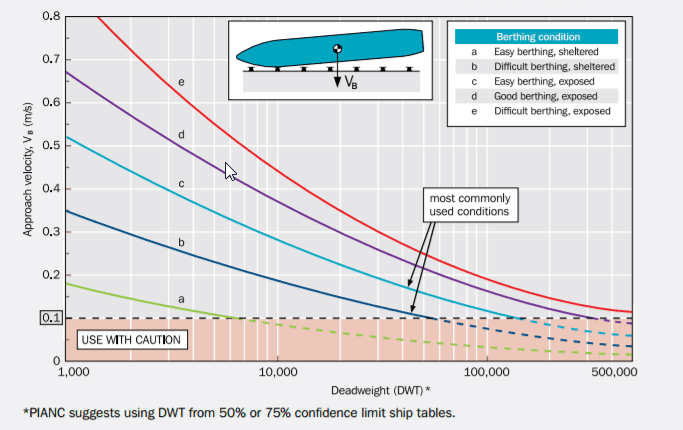
Estimating the berthing velocity (source: www.trelleborg.com)
In fact, there are other factors which come into play in determining the Impact Energy. These are
- Added mass factor – due to mass of water moving along with ship
- Eccentricity factor – due to ship not berthing parallel to the jetty
- Softness Factor – whether the fender is soft or hard
- Berth Configuration factor – whether the jetty/quay is solid or open type
These will be taken up in detail in Part 2 of this article.
Normal and Abnormal Berthing Energies
Berthing energy is classified as ‘Normal Berthing Energy’, and ‘Abnormal Berthing Energy’. Normal Berthing Energy is the energy capacity of the fender required for regular operations during the lifetime of the berth/vessel. Abnormal Berthing Energy is the energy capacity required to take care of rare incidents in which there can be significant fender damage, e.g., rare environmental hazards, or exceptionally large ships encountering the berth etc.
By now, we know that the fender is to be designed to absorb a Berthing Energy which depends on the size of the ship and other factors. Let’ see the concepts of Side and End berthing before we move on to see how to select the right fender.
Section B: Fendering methods – Side Berthing or End Berthing
A ship berthing with a jetty/quay can berth with either its side or its end aligned to the jetty/quay. There can be other types of berthing like Dolphin berthing or Locks, but we’ll limit ourselves to Side and End berthing for this article. The selection of berthing type will depend on factors like the ship size, berth type and size, and the ease of approach.
The figure below demonstrates the two different types of berthing:
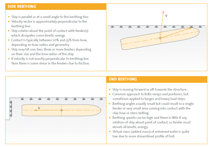
Types of Berthing (Source: www.rubberstyle.com)
Section C: Selecting the right fender
Selecting the right fender requires a step-by-step approach which we delineate below:
Step 1 – Homework
Before evaluating the properties of fender needed, we need to do some background work to gather relevant information through a study of two broad aspects:
- Environment in which the fender is going to operate. Some important factors are –
- Berth construction
- Available space for fenders
- Seabed depth
- Tidal ranges
- Corrosion levels
- Range and characteristics of ships which it is going to serve. Some important factors are –
- Ship sizes to be served
- Ship types – a passenger vessel will have different fendering requirements than a Ro-Ro vessel
- Approach speeds
- of points of contact
- Frequency of berthing
- Mode – Side/End berthing
- Bow construction/flare angles of ships served
Step 2 – Estimating the berthing energy
The next step is to estimate the berthing energy required to berth the vessel. The berthing energy is the most critical test of a fender. Whatever be the shape, size or material of the selected fender, it should be have the capacity to absorb the impact of the berthing energy. The fender’s capacity should be sufficient for it to absorb the Abnormal Berthing Energy. The detailed calculations for estimating the berthing energy shall be taken up in the Part 2 of this article.
Step 3 – Fender selection
With the information from Step 1 available, and with the required berthing energy calculated, we can now select the right fender.
Selecting a fender is an exercise with multiple factors and constraints to be managed.
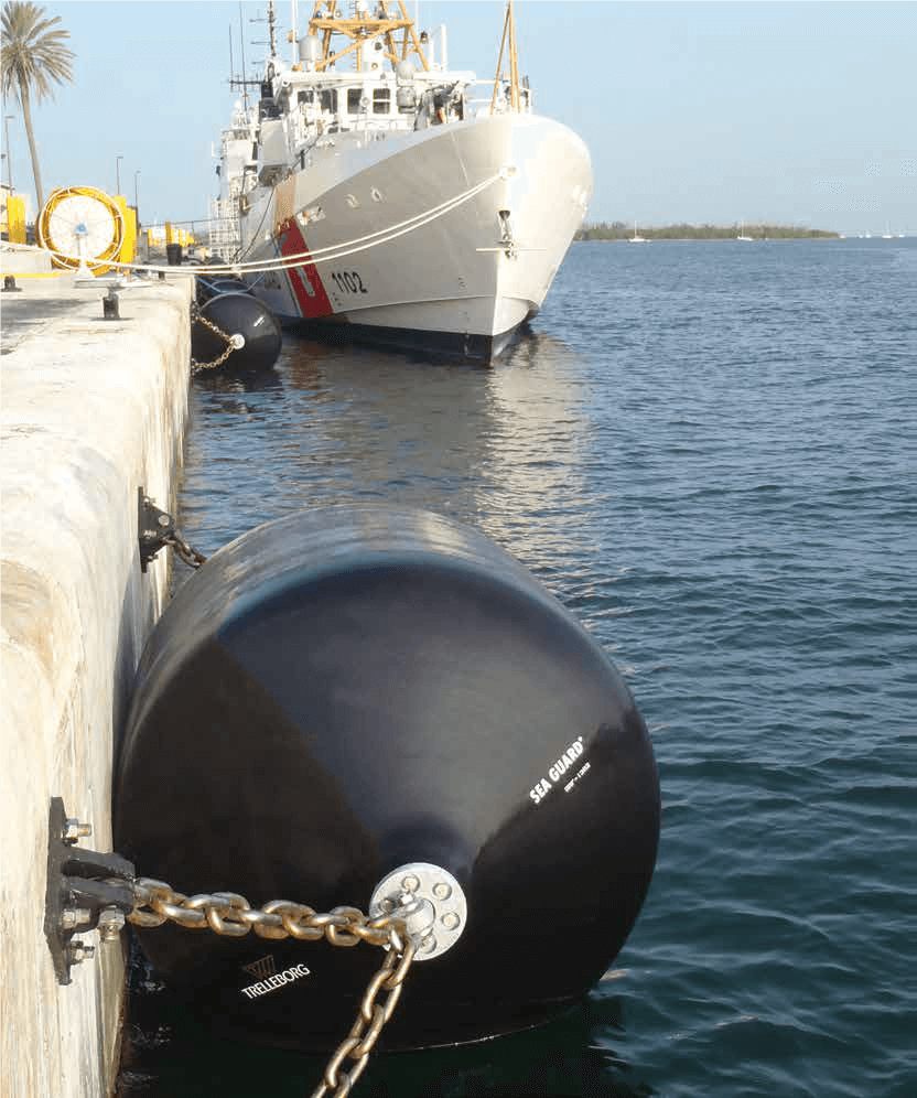
- Fender type and shape – Fenders can be fixed to the structure (e.g. in a berth/jetty) or floating (e.g., pneumatic fenders on a ship). This is best decided based on a case-to-case basis depending on the design requirements at hand. For example, for ship to ship berthing, pneumatic or foam fenders are generally used. These are usually hanging on the side of the vessel through chains and are lowered down when approaching the berth. On berth/jetty, a fixed type of fender is generally used, but it can also be floating one for berths with high tidal variation.
Fenders can also be of different shapes. Flat panel fenders are generally used on berths, while cylindrical/pneumatic fenders are used on ships. Pneumatic fenders are filled with air at high pressure to provide the absorption energy needed. They are generally used in ship-to-ship berthing and have a low deflection and high energy capacity. Foam fenders can be cylindrical or spherical and have a core of foam and an outer skin of a polymer. Donut fenders are designed to simply slip on a pile and float up and down on the pile with tidal variations. However, the selection really depends on the design needs of the case at hand.
- Fixed fenders – Cell fenders, V-type fenders and cylindrical fenders are generally used as fixed fenders.

V-type fender (source: www.theartofdredging.com)
Cell type fender (source: www.trelleborg.com)
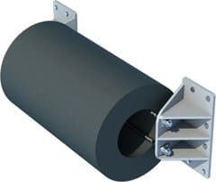
Cylindrical fixed fender (source: eurotechbenelux.com)
- Floating fenders – Foam fenders, donut fenders and pneumatic fenders are generally used as floating fenders.
Foam Fender (source: www.trelleborg.com)
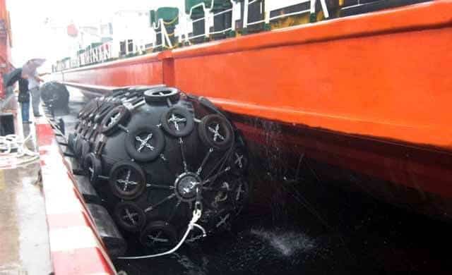
Pneumatic Fender (source: www.airbag.cc)
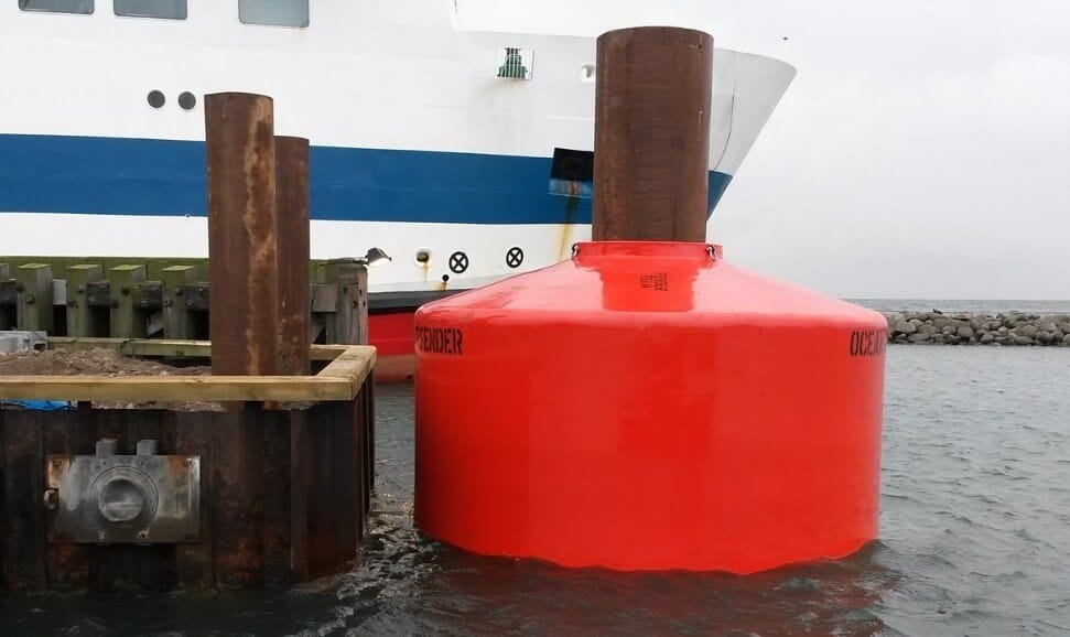
A donut fender (source: www.shibata-fender.team)
- Checking the energy capacity – The fender should have energy capacity to absorb the Abnormal Berthing Energy. Allowances are required to be made for factors like temperature, velocity, compression angle, manufacturing tolerance etc. The fender’s energy capacity is measured in terms of RPD, or Rated Performance Data which is its capacity at a temperature of 23 degrees Celsius, 0.15 m/s impact velocity, 0 degrees compression angle and mid-tolerance. For values of temperature, velocity, compression angle and tolerance differing from these standard values, we need to apply allowance factors. The fender energy capacity is calculated as
EF = ERPD x fTOL x fANG x fTEMP x fVEL
Where
EF is the minimum fender energy
ERPD is the fender energy at Rated Performance Data (RPD)
fTOL is the allowance factor for fender manufacturing tolerances
fANG is the allowance factor for compression angle. The minimum energy occurs at the maximum compression angle
fVEL is the allowance factor for the impact velocity other than 0.15 m/s. The fender’s minimum energy occurs at the maximum impact velocity
fTEMP is the allowance factor for temperatures other than 23 degrees C. The minimum fender energy occurs at highest temperature.
Each of the above factors can be determined from curves specific to the fender being selected.
- Checking the fender reaction – The fender is not only supposed to absorb the berthing energy, but it’s impact on the ship/berth structure too should be minimal. The reaction force is the force that the fender imparts on the vessel/berth. This reaction force must be less than the structural capacity of the vessel/berth. The maximum fender reaction is given as:
RF = RRPD x fTOL x fANG x fTEMP x fVEL
Where
RF = maximum fender reaction
RRPD = fender reaction at RPD
The rest of the terms are as described above.
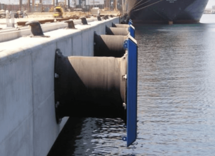
- Fender Spacing and contact – Spacing of fenders is specified by ‘fender pitch’ which is the distance between two adjacent fenders. The spacing of fenders is critical – fenders spaced too far apart may lead to the vessel hitting the berth. The spacing of fenders should be determined by studying the complete range of vessels expected to visit the berth. The spacing is determined from properties like bow radius and length of vessel. Generally, it is not recommended to exceed a spacing of 10 – 15 m. The figure below demonstrates the fender pitch (P).
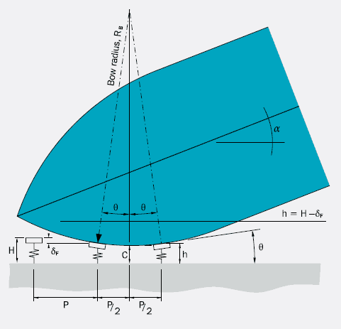
Fender Pitch (source: www.trelleborg.com)
- Fender Contact
The fender selection depends also on how many fenders are in contact with the vessel. The berthing energy is accordingly divided among the fenders in contact, depending on the extent of deflection of each fender.
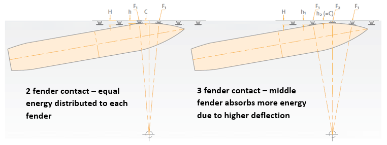
Fender contacts – 2 Fender and 3 Fender contact cases (source: www.rubberstyle.com)
- Fender material and construction –
For panel fenders, the panels are generally made of weldable structural steel. The actual material selected depends on the design requirements. For heavy duty environments, higher grade steels may be used. The panels are then covered with low-friction pads to minimize damage due to frequent encounter with the ship’s hull. Low friction material is important for longer life and lower maintenance cost of a fender. Generally, Ultra High Molecular Weight Polyethylene (UHMW – PE) pads are fitted to fender panels. They have good wear resistance, low-friction and long life.
For pneumatic fenders, generally rubber fenders are used. Natural rubber, synthetic rubber or a blend can be used. Synthetic rubber is generally more weather resistant than natural rubber. EPDM (Ethylene Propylene Diene Monomer) rubber is a special purpose rubber with weather resistance and long life. However, almost all rubber fenders have poor resistance to oil, fuels, hydraulic fluids, acids and most hydrocarbons.
- Other Factors – Depending on the shape and type of fender selected, there will be other factors which we will need to consider while selecting the right fender.
Accessories design – Fender chains, shackles, nuts, pins, wheels, rollers, brackets etc. should also be designed to support the fender weight and prevent excessive movement of the fender.
Hull pressure, belting and bending Moment – The hull pressure against the fender affects the internal structure of fenders made of steel panels. For cell fenders installed on the berth, the bending moment imparted by the hull pressing against the fender should be within the strength of the fender. Different loading cases need to be analysed and the structural strength of the fender needs to be assessed for each case
Paint and corrosion prevention – Fenders are required to function in harsh and corrosive marine environments. The fatigue due to frequent berthing adds to the corrosivity. Similarly, high temperatures in tropical zones and ship vibrations can be additional factors which lower the life and performance of fenders. The material of the fender must be reliable and corrosion resistant. Several methods can be used
- Galvanizing of all steel pads or accessories like chains, shackles etc
- Using sacrificial anodes
- Using protective paint coatings – the standard followed is ISO 12944
- Using stainless steel fixtures
Availability, cost and spares – the availability of the selected fender design, its cost, and availability of spare parts are other important factors to be considered.
Testing – Fenders can be tested in the factory before being purchased (Factory Acceptance Test or FAT). Tests can be setup to measure energy absorption and reaction force. Testing can be done in accordance with PIANC guidelines.
Section D: Standards and guidelines
ROM 2.0-11 Actions in the Design of Maritime and Harbor Works
ROM 3.1 Actions in the Design of Maritime and Harbor Works: this is the latest version of the Spanish ROM available in English
BS6349-4:2014 Code of Practice for Design of Fendering and Mooring Systems
EAU 2004 Recommendations of the Committee for Waterfront Structures
PIANC 2002 Guidelines for the Design of Fender Systems: 2002 Marcom Report of WG33
ISO EN 12944 Standard for Corrosion protection of steel structures by protective paint systems
ASTM An international standards organization that develops and publishes voluntary consensus technical standards for a wide range of materials, products, systems, and services
EN 10025 A set of European standards which specify the technical delivery conditions for hot rolled products of structural steels
JIS G-3101 A Japanese material standard for hot Rolled steel plates, sheets, strips for general structural usage
PIANC report WG121 Harbor approach changes design guidelines from 2014 incl. the latest design information on vessels
OCIMF Ship to Ship Transfers – Considerations Applicable to Reverse Lightering Operations
Disclaimer: This post is not meant to be an authoritative writing on the topic presented. thenavalarch bears no responsibility for any incidents or losses arising due to the use of the information in this article in any operation. It is recommended to seek professional advice before executing any activity which draws on information mentioned in this post. All the figures, drawings and pictures are property of thenavalarch except where indicated, and may not be copied or distributed without permission.

Excellent and useful.
Hi Parimal
Many thanks. Please do keep visiting
Hello Team, very interesting. Suppose you have 2 berths constructed in the same way, so they both have the same resistance from the civil works point of view. The berths were built for a certain design vessel. But now you want to put a larger vessel. Would replacing the fender system for a more robust one allow for safe berthing of the bigger vessel?
Thank you
Hi Roberto
Thanks for the comments. A robust fender system will definitely be needed, alongwith a re-evaluation of the existing berth structure itself to be able to take the larger vessel’s loads. A mooring analysis coupled with FEA should do the job. We carry out such assessments, and you’re welcome to get in touch. Thanks
Prem Shankar
TheNavalArch
Dear Sir,
Namaskar. There are two fender in different elevation . For structural design whether same reaction need to be applied at two fender location or reaction will be different . if reactions are different then how calculation can be made . Please help
Deeply thanks for letting me know about valuable ship knowledge.