(To read Part 2, click here)
This is the first part in the 3-part series on Pipe Transportation. In this part we will discuss about pipes and their properties.
In this article, we will talk about the transportation of pipes on ships. Pipes are needed for various uses in both onshore and offshore environments. They are extensively used in laying pipelines on ground and sea bed. In this article, we will limit ourselves to pipes required for laying pipelines on the sea bed for transporting oil and other fluids. However, the pipe transportation principles remain the same and can be easily applied to any other scenario.
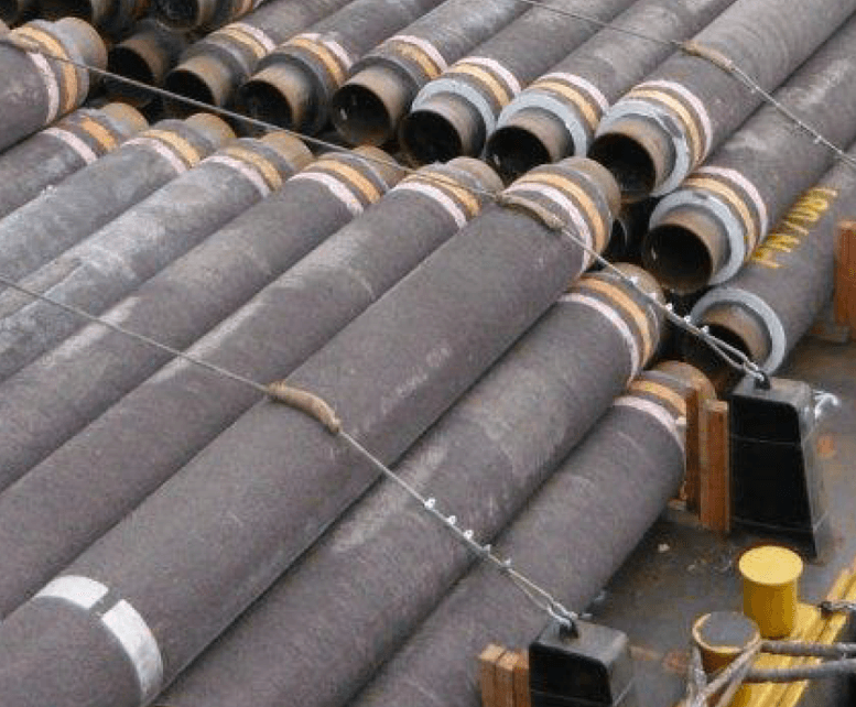
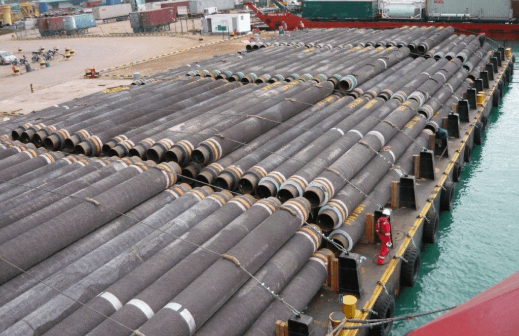
Pipes may be fabricated at location A, while they may need to be laid on the sea bed at location B. If the number of pipes to be transported is high, then ships or barges need to be deployed for transporting these pipes. To imagine it in the simplest way, it involves just loading pipes on the deck or cargo holds of a ship (the picture above has deck loading), and taking the ship to its final location. In real terms, though, it is a niche operation requiring experienced personnel and skilled engineering to drive it to success.
This article gives an insight into the mechanisms involved in large scale pipe transportation operations, and the engineering which goes behind it.
We will divide this article into sections
- SECTION 1 – We will talk about pipes and their properties
- SECTION 2 – We will talk about a pipe transportation project’s planning and engineering. It will be further subdivided into
- Section 2.1 – Establishing the scope
- Section 2.2 – Planning and Scheduling
- Section 2.3 – Engineering
- Section 2.4 – Operation
In this Part, we will cover Section 1. In Part 2, we will cover Sections 2.1 & 2.2, while in the Part 3, Section 2.3 & 2.4 will be covered.
References
Following references have been used in this article
[1] GL Nobledenton Guidelines for Marine Transportation, ND-0030
[2] GL Nobledenton Guidelines for Marine Lifting and Lowering Operations, ND-0027
[3] ABS Rules for Building and Classing of Steel Barges
[4] Roark’s Formulas for Stress and Strain
[5] DNV-OS-H103 Modelling and Analysis of Marine Operations
SECTION 1 – PIPES
Let’s begin by talking about pipes. In the pipe transportation industry, they are also called ‘joints’.
Pipe Sizes – single, double, triple, and quad joints
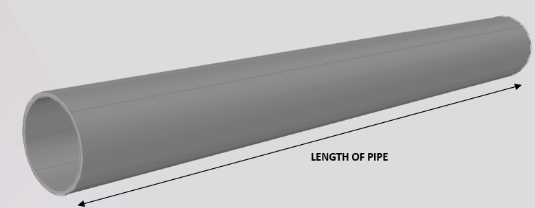
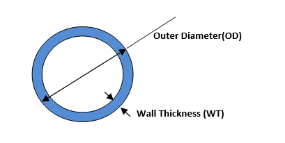
Pipes can be of different sizes. Their size is defined by following two parameters (see Figure) –
- Outer diameter
- Length
- Wall thickness
Pipes can be of different diameters and wall thicknesses depending on their usage. In terms of length of pipes used in pipelaying, there is some standardization. A single joint is generally 40 Ft (12.2 m) in length. There can also be double, triple, and quad joints with lengths 80, 120 and 160 Ft respectively.
Pipe Coatings – Bare Pipes, CWC and Corrosion Coating
Pipes are usually made of steel. Pipes made of only steel without any additional coatings are called ‘bare pipes’. However, a steel pipe may be coated with concrete for providing negative buoyancy to the pipeline on the sea bed. This provides submerged weight stability to the pipeline, and protects the corrosion coating of pipes. The concrete coating is called as Concrete Weight Coating, abbreviated as CWC.
Pipes may additionally be coated with a thin anti-corrosion coating to protect them from the highly corrosive marine environment. There may be additional layers of other kinds of coatings on pipes depending on the usage.

Stacking of pipes – Nested Diameter, Pipe Yield Stress and Stacking height limit
The next important aspect of pipes is the way they are stacked for storage or transport. Pipes can be stacked on above another forming different tiers or ‘stacks’. The pipes of the second tier (the one just above the bottom tier) will sit in the grooves created in the bottom tier. Similarly, the third-tier pipes will sit in the grooves of the second tier and so on. If we continue like this, a trapezium shaped stacking will be created, as shown below:
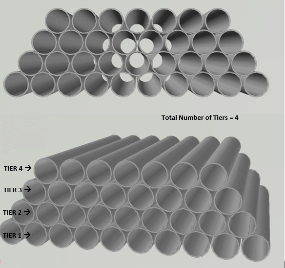
Nested OD
This type of stacking is called ‘nested’ stacking (pipes sitting in grooves). With the pipes sitting in the grooves, the total height of a stack of pipes is less than the number of stacks times the diameter. This gives rise to the term ‘Nested Diameter’. Nested outer diameter (Nested OD) is the total height of the stack divided by the number of stacks. This is lesser than a pipe’s outer diameter.
Nested Diameter (Nested OD) = Total Height of Pipe Stack / Number of stacks
Below we will derive a simple formula for Nested OD.

In the above figure, R is radius of pipe = Pipe OD/2.
h = vertical distance between two tiers = √3/2 x pipe OD
If the number of tiers is n, then
Stack Height, H = R (for bottom tier lower half) + (n-1) x h + R (for top tier upper half)
- H = pipe OD + (n-1) x √3/2 x pipe OD
- Nested OD = H/n
Stacking Height Limit
This naturally raises a question: how high can we keep stacking pipes safely? As we keep stacking, we realize that the bottom tier of the pipe takes increasingly higher weight. The stacking height is determined by the maximum number of stacks which we can add before the bottom tier yields. How do we measure this yielding?
- For bare pipes, the yield limit is the yield stress of steel of pipe
- For concrete pipes, either the concrete or the steel may yield. The first one to yield governs the yield limit
- For pipes with anti-corrosion coating, the coating may also yield, but it is usually not governing in comparison to steel and concrete yielding.
Let’s talk a bit more in detail on calculating the stacking limit by taking the case of bare pipes. For the bottom tier of pipes, the following loads are acting –
- Load due to pipes above
- Self-weight
These two are depicted below
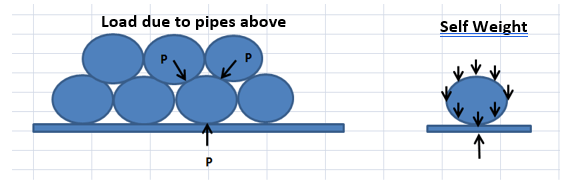
From the above, and based on Roark’s formulae for the two load cases above, the limiting number of tiers can be calculated. For more on Stacking Height Calculation for bare pipes, you can see thenavalarch’s product Pipe Stacking Height Calculator.
That brings us to the end of Part 1. In Part 2, we will discuss planning and scheduling of pipe transport projects.
Disclaimer: This post is not meant to be an authoritative writing on the topic presented. thenavalarch bears no responsibility for any incidents or losses arising due to the use of the information in this article in any operation. It is recommended to seek professional advice before executing any operation which draws on information mentioned in this post. All the figures, drawings and pictures are property of thenavalarch except where indicated, and may not be copied or distributed without permission.

Dear Sir
I am very interested to buy all Guidelines and best practice for pipes transportation and lashing and stowage thisvtypebo cargo
Dear Sir
I am very interested to buy all Guidelines and best practice for pipes transportation and lashing and stowage thisvtypebo cargo
Excellent