
By Alan Crowle, BSc, MSc, MScbyRes, CEng, CMarEng, FRINA, FMAREST, FSCMS
University of Exeter, College of Engineering, Renewable Energy Group
Email: ac1080@exeter.ac.uk
Introduction
Launching of steel jackets is a common method of installing large fixed, offshore structures. The launch of the jacket structure from the transportation barge is one of the most dramatic phases of any offshore installation. Launch jackets are used as substructures for offshore production of oil and gas facilities and for the support of large electrical substations.
This article discusses the analysis techniques used to determine the launch characteristics of offshore structures and the requirements for offshore equipment used during installation.
The analysis of the jacket launch from a barge is complex. The objective of the launch analysis is to define a method to transfer the jacket from the barge to the water in the smoothest and safest manner possible. This process involves minimising jacket and barge stresses and reducing the sensitivity of the launch to small variations to the established configuration. Initially, a choice of barges has to be made in order to make them suitable for a particular jacket design. The naval architect then proceeds with the launch analysis by deciding upon the temporary buoyancy requirements for the jacket. The structural analysis assesses the forces acting on the jacket, which are self-weight, buoyancy, drag, inertia, friction, barge/rocker beam reactions, hydrodynamic forces and structural forces.
The principal stages for a jacket launch are shown in Figure 1:
- Stage 1: Winching along the barge to overcome friction.
- Stage 2: Sliding.
- Stage 3: Point of rotation.
- Stage 4: Rotating and sliding.
- Stage 5: Jacket clear of barge.
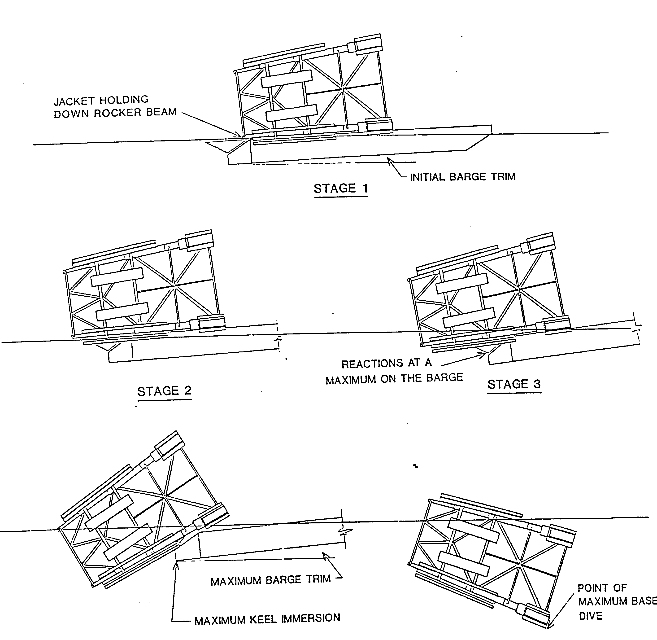
The most critical stage for both jacket and barge is usually rotation of the jacket on the tilt beams (Stage 3). Stresses in the barge are at a maximum due to both the unfavourable longitudinal distribution of weight and the concentrated local loadings at the tilt beam supports. Typically, launch barges are highly reinforced at the launch end in order to carry these high tilt beam reactions.
Both the tilt beam and hull girder loadings may be moderated to some extent by the prudent positioning of ballast prior to launch. Increasing the barge trim has the effect of immersing more of the jacket early in the launch, which results in an increased buoyant force that reduces the load on the barge. Whilst high trim tends to add to hull bending stress, placing the ballast near the middle of the launch barge reduces the inherent hogging moment on the barge.
Jacket rotation is also a critical stage in the launch process due to the fact that the jacket is supported only by a short span of the beam. In general, the more of the jacket that is immersed, the lower the jacket stress.
The barge’s transverse and longitudinal stability will decrease rapidly if the barge is allowed to trim to such angles that either the bow emerges or the stern submerges in the water. High trim increases the possibility of self-launch before all sea-fastenings are cut, which is dangerous to personnel on the barge.
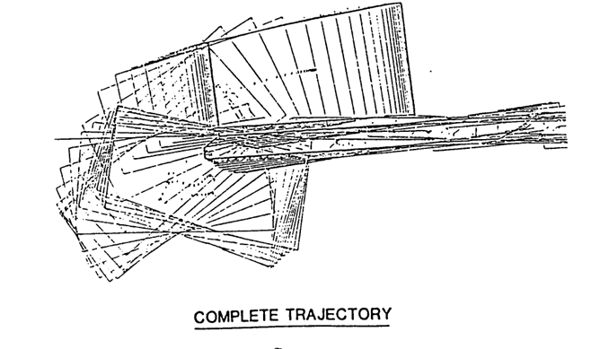
Whilst the launch operation is of short duration and generally performed under good weather conditions, the possibility exists that the jacket may hang up during launch and remain on the tilt beams for some periods of time. A major concern is that the jacket may skew on the launch rails or launch in an unpredictable fashion. Either of these situations can lead to damage of the jacket or barge. Figure 2 shows the overall jacket trajectory.
Two other items of importance addressed by a launch simulation concern the maximum submergence of the jacket as it clears the barge (Stage 5) and the final attitude of the structure in the water.
Barge choice
One of the first tasks is to identify suitable barges for launching the jacket and then to optimise the quantity and position of the ballast for achieving the launch. Barge choice will have some effect on rocker reactions and hence on the structural loadings on the barge and jacket.
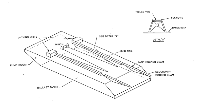
A typical launch barge will be fitted with skid rails, rocker arms (possibly including secondary rocker beams), a ballasting system and jacking or winch systems, as shown in Figure 3.
On choosing a launch barge, the following major technical considerations need to be taken into account. The jacket has to fit on the barge without any possibility of clashing. The barge has to be suitable for load-out at any construction yard, taking into account tidal variations, minimum water depth and the width of dredged channels.
Barge strength has to be checked in load-out whether it is a floating or a grounded load-out. Barge strength is also considered for the ocean voyage and in the launch sequence, especially at the point of rotation.
The barge is to be suitable for transportation of the jacket from the construction yard to the launch site. During the launch there are restrictions on:
- Keel immersion of the barge.
- Rocker beam reaction.
- Barge strength.
A barge with a high pumping capacity would be an advantage so that the barge can proceed quickly from transportation ballast to launch ballast. A barge draft of about 60-65% of barge depth and a trim of 4% is usual. A draft of up to 80% of barge depth is possible if barge strength is adequate.
If the jacket is likely to have protruding elements at the base, great care should be taken to ensure that they are not knocked off during launch. Normally the launch ballast will be greater than the transportation ballast requirements. In order to cut down the time required to ballast the barge for launch, water should not be shifted within the barge. Space is required at the forward end of the barge for skid rail jacking units.
The jacket skid rails should be on top of the rocker arms prior to commencement of launch. For a barge with secondary rocker arms, the jacket should sit on top of them. The barge may also be used to transport items removed from the jacket after installation, such as auxiliary buoyancy, upending control capsule, upending rigging and pile followers.
Jacket auxiliary buoyancy
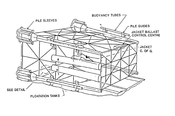
In order to execute a safe launch and upending, a jacket will normally be fitted with auxiliary buoyancy, as shown in Figure 4. Typically, over 10% of the launch weight consists of buoyancy tubes and flotation tanks. During launch, the main functions of the auxiliary buoyancy are to reduce rocker reactions and to provide a safe bottom clearance and a stable equilibrium position when the structure comes to rest.
Methods of analysis
The primary requirements of launch simulation software are to analyse the dynamic behaviour of a jacket and barge and to transfer member loads for jacket stress analyses to a structural analysis program. Ideally, the software should have the capability of varying the length of the time steps used in the integration of the equations of motion. More importantly, the launch software should possess a facility to plot a time history of the output.
The software performs a dynamic time history analysis of the launch from the initial barge trimming through to jacket-barge disengagement and final resting in the water. At regular time steps, a report of the jacket and barge status is produced, giving such details as:
- The position, velocity and acceleration of the jacket and barge centre of mass.
- The distance the jacket has skidded relative to the rocker pin.
- The total out-of-balance forces (reactions).
- Buoyancy, drag and inertia forces on the jacket.
The trajectory is used to determine the time intervals, or “snapshots”, at which detailed member load reports are to be generated.
Early launch software was only able to consider the predominant two-dimensional motions. This software is still used for parametric analyses to consider the effects of variations in barge draft and trim and positions of the jacket on the barge. The industry now uses three-dimensional analysis, which enables the effects of barge roll to be assessed and hence the differences in reaction between port and starboard rocker arms to be determined. Additional software is required to calculate bending moments on the barge and to assess stability of the jacket/barge condition.
Model tests
The analytical techniques for predicting jacket launching characteristics have been used extensively, but there is very little knowledge of launch characteristics at full scale, especially rocker beam reactions.
Launch constraints
Ballast constraint curves are established by performing parametric analyses of the barge mean draft and initial trim whilst keeping the jacket weight, centre of gravity and friction coefficient constant.
The boundaries of the launch conditions are:
- The ballast space limit.
- The maximum allowable keel immersion.
- The maximum allowable barge trim, usually about 10 degrees.
- The maximum allowable primary rocker beam reaction.
- The maximum allowable secondary rocker beam reaction.
- The maximum allowable barge initial trim, limited by the static friction coefficient.
- Minimum GM, initial stability.
- Summer load line draft, which may have to be exceeded for a short time during launch.
- Maximum dive depth of the head of the jacket.
- Maximum dive depth of the jacket base.
High rocker reactions can be overcome by:
- Change in jacket temporary buoyancy.
- Increase in the initial trim.
- Increase in barge ballast.
An initial barge trim angle of between 4 and 5% is normal as the static friction can be as low as 5%. The dynamic coefficient of friction can be as low as 3.5% for greased timber on Teflon.
Offshore operations
The severest restriction on the offshore launching operation is the environmental conditions for personnel boarding the barge. These are normally limited to sea states of less than two metres significant wave height.
Structural analysis
The forces acting on the jacket during the launch sequence are:
- Self-weight.
- Buoyancy.
- Hydrodynamic drag and inertia.
- Structural inertia.
- Barge/rocker beam reactions.
- Friction.
As the jacket slides off the barge and into the water, the magnitude, distribution and direction of the above forces change in each member. The purpose of the structural launch analysis is to confirm the adequacy of the jacket members when subjected to the distribution and combination of the above forces at any stage of the launch process.
The structural analysis cannot continually monitor the stress patterns in the jacket throughout the launch. Therefore, snapshots of the loading on the jacket are taken along the jacket’s trajectory, for which detailed reports of applied member loads are produced. These will comprise the load cases in the subsequent analyses.
The structural analysis for launch is complicated by the fact that the support conditions of the jacket change for each launch position. The adopted method for this analysis is to perform a separate stiffness analysis for each launch position with the actual support conditions accurately modelled.
The load cases for which the structure is to be analysed are selected after the naval architectural launch analysis has been performed. The selection is made on the basis of high rocker pin reactions corresponding with “hard points” on the launch leg. In general, these will be when stiffened-up nodes in the launch leg are directly opposite the rocker pin, as very high local loads are generated.
The structural model for the structural and hydrodynamic analysis consists of all the structural members plus additional joints along the launch legs to enable more accurate modelling of the rocker beam contact and launch leg joint eccentricities.
The self-weight of the jacket is generated by specifying the diameters, wall thicknesses and material density of the tube. The stick weight (nominal member section x length x material density) will considerably underestimate the true weight. Therefore, a combination of modifying the material density (to account for extra weight evenly distributed over the jacket, such as anodes and stiffening) and applying point masses for major additions such as pile guides and caissons is performed on the model. The centre of gravity must also be correctly placed, and this is done by the application of small point masses around the jacket.
The buoyancy of the jacket is generated from the member diameter and water density. For equivalent tubulars (for example, pile sleeve assemblies and conductor ladders), the diameter is determined for the correct member weight. To achieve the correct centre of buoyancy, small point buoyancies are distributed around the jacket.
The drag and inertia forces are generated using Morison’s equation and velocities and accelerations derived from the time-history analysis. The nominal coefficients are:
| Coefficient | Nominal value |
|---|---|
| Drag (Cd) | 0.7 |
| Inertia (Cm) | 2.0 |
Where equivalent members have been used, equivalent Cm and Cd values are derived by factoring the coefficients in accordance with the change in volumes and areas respectively.
All primary members in the launch analysis model are checked to codes as appropriate. Punching shear checks are also made on tubulars.
From the hydrodynamic launch analysis, the maximum diving depth of members can be determined, and they need to be checked against hydrostatic collapse. Attachment of auxiliary buoyancy requires structural checks. Many members are subject to large slam loads during launch, and their structural adequacy needs to be checked for this condition. Corrections for appurtenances, particularly temporary buoyancy, need to be checked for a variety of attitudes.
Conclusions
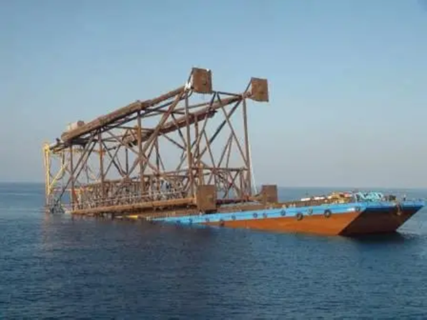
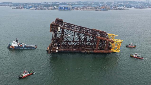
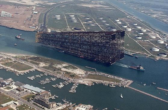
Jacket launch is a standard method of installing large jackets offshore. Some jackets are quite small, such as 2,000-tonne wellhead jackets (Figure 5). Larger jackets are shown in Figure 6. The largest jacket launched is shown in Figure 7.
Acknowledgements
Alan Crowle thanks his colleagues at the University of Exeter for their assistance in preparing this article and, in particular, for the assistance of Professor P. R. Thies.
Related reading
- Offshore Installation Vessels Stability Considerations
- Global Wave Statistical Analysis and Its Use in Deepwater Operations
- A Simplified Method of Performing Fatigue Analysis of Offshore Structures
Continue exploring practical naval architecture and offshore engineering guidance: visit TheNavalArch for more technical articles, tools and engineering resources.
Great article, a good introduction to the the naval architectural design issues of a launch jacket. You could make reference to existing marine standards, like DNV-ST-N001.
Would also be good to discuss how this process fits in the overal design of the jacket. E.g. the naval architectural design process requires to consider a matrix of weights and CoG which narrows down as the design matures.
On my site you can find a nice video of a launch. https://www.orca-offshore.com/project/ace-jacket-offshore-support/