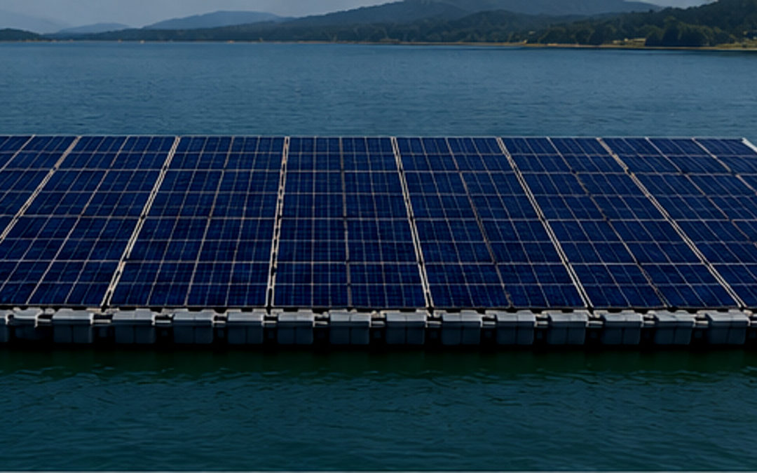
Floating PV is one of those technologies that looks almost obvious
once you see it: put solar panels on unused water, save land, reduce
evaporation, and connect near existing hydropower or grid
infrastructure.
It is now meeting the part of reality that does not appear in early
concept slides: storms, moving water, tired connections, awkward access,
and the morning after an abnormal event.
The sharper question is what happens when a lightweight, modular,
electrically active asset starts behaving like floating infrastructure
rather than solar equipment installed on water.
Reported incidents do not give us every root cause. Most public
reports never do. But they do show enough patterns to ask better
questions: what moved first, where did the load go next, what remained
energized, and how quickly could the asset be reached and recovered?
The first lesson is scale. Once a floating solar field becomes large
enough, it stops being a neat layout on a drawing and starts becoming a
moving structural system.
Floating PV
Growth and Water Surface Occupation
According to IEA PVPS, floating PV capacity grew from just above 1.6
GW at the end of 2018 to 7.7 GW by the end of 2023. Almost 90% of that
capacity is in Asia, with China representing close to half of the global
installed base.
That sounds like a market statistic. But what does it actually look
like on water?
Using a broad order-of-magnitude range of 0.8–1.2 hectares per MWp,
global floating PV at the end of 2023 may already represent around 9000
hectares of floating equipment.
Now imagine those nine thousand football pitches not as grass, but as
modules, floats, cables, connectors, walkways and mooring lines. Not
fixed to the ground. Moving.
The Huaneng Dezhou Dingzhuang Floating PV project in Shandong, China,
reached 320 MW and was reported as the world’s largest floating PV
project when completed. Using the same rough surface estimate, a project
of that scale could occupy in the order of 250–380 hectares of water
surface.
That is approximately the size of the City of London — but floating,
electrically active and exposed to weather.
That is why the incidents matter. They are stress tests written by
weather.
Reported
Incidents: Why the Risks Are Not Theoretical
Publicly reported incidents in Japan, Albania, India and Taiwan show
recurring themes: typhoon or storm damage, platform movement, floating
debris, partial submersion, fire exposure and difficult post-event
recovery.
Floating PV is not a road without bumps. Things happen in operating
plants. Small incidents, temporary damage, cable issues, access problems
or local repairs often remain inside the project and never reach the
public domain. Anyone who has worked around real assets knows this.
The cases that become visible are usually the ones that escalate:
damage spreads, debris appears, fire is reported, recovery becomes
difficult, or the event reaches regulators, insurers, local communities
or the media.
Some involve reservoirs, ponds, coastal exposure, and not all use the
same floating architecture. That matters. Floating PV is not one
technology; it is a family of floating structures, mooring concepts and
electrical layouts.
The useful lesson is not to wait for the spectacular failure. The
smaller signals usually appear first.
A compact incident map helps keep the discussion
grounded:
| Date | Location | Reported event | Engineering reading |
| 2016 | Japan, Kawashima | Typhoon damage to panels/racks | Edge zones and rack connections deserve storm-detail review. |
| 2019 | Japan, Yamakura Dam | Typhoon damage followed by fire; panels reportedly stacked | Mechanical damage can become electrical/fire exposure when DC circuits re-energize. |
| 2021 | Albania, Banja Reservoir | Floating unit severely damaged and partly submerged | Buoyancy, membrane integrity and recovery planning matter after abnormal loads. |
| 2024 | India, Omkareshwar Dam | Storm damage reported at large FPV project | Large reservoirs should not be treated as benign water by default. |
| 2025 | Taiwan, coastal FPV / Typhoon Danas | Floating solar damage, debris and recovery concerns | Coastal FPV becomes a marine debris, navigation and public-risk issue. |
The table is a map of repeated engineering questions: what moved,
what carried the load, what became energized, and how the asset was
recovered.
Failure
Mechanism 1: The Real Load Case Begins After the First Deformation
Wind loads are often reviewed against the initial geometry of the
floating island. That is necessary, but it may not be the condition that
hurts the project most.
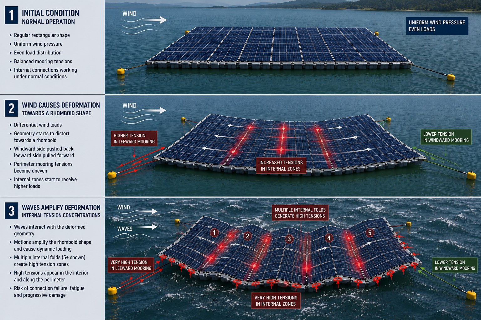
Under strong, non-uniform wind, a large floating array may stop
behaving like the clean rectangle assumed in the model. One side moves
first. A corner rotates. The field starts tending towards a skewed
shape, closer to a rhomboid than to the drawing everyone approved in the
meeting. At that point, local angles, exposed edges and restraint
conditions have already changed.
Once the geometry changes, the wind is no longer acting on the same
structure. Local exposure changes. Pressure distribution changes. Areas
that were supposed to share loads quietly may start attracting different
demands.
Waves can amplify the problem. Wind may start the deformation, but
waves keep changing the position and attitude of the field. The result
is not just a higher load; it is an evolving load case.
For large or exposed FPV plants, the design model should not remain a
theoretical exercise after commissioning. Key mooring lines can be
instrumented with load cells or strain gauges, and selected points of
the floating island can be tracked with high-precision GPS. During the
first months of operation, this data can show how the island actually
moves, which lines take more load, and whether the real behaviour
matches the design assumptions and the model. That feedback allows
engineers to validate the system and take action, improving inspection
priorities, redesign if applicable, and preparing the plant before a
more severe event arrives.
The practical review question is simple: once the floating
field starts changing shape, does the design model still represent
reality?
If the answer is uncomfortable, the next question is even more
important: where does that deformation go?
Source illustration supplied by the author.
Failure
Mechanism 2: When the Mooring Holds, the Island Still Has to Deform
Safely
Anyone who has tried to hold a large wet tarpaulin in the wind knows
the problem. You may control the corners, but the middle still moves,
twists and pulls in its own way.
Floating PV can behave in a similar manner.
Mooring keeps the plant within position. It does not automatically
keep the floating island internally healthy.
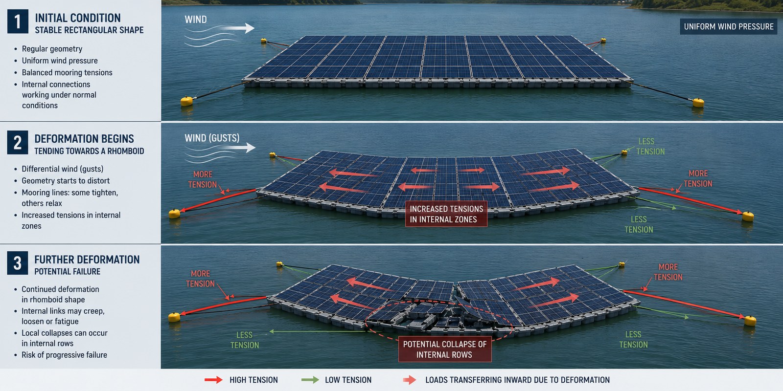
During an extreme event, the perimeter may remain controlled while
the interior absorbs deformation. Loads can then concentrate in two
areas: at the perimeter, where a flexible field meets restraint, and
inside the island, where rows, floats and connectors must accommodate
differential movement.
The perimeter problem is a transition problem. Perimeter elements are
usually designed to be stronger because they connect the floating field
to the restraint system. But if one perimeter section is damaged,
displaced or locally overloaded, it can become the starting point for
progressive damage.
That first damaged zone acts as a new stress concentrator. Instead of
distributing load smoothly, the system may start pulling on the next
connection, then the next, and then the next. In some configurations,
the failure can start opening the floating field like a zipper.
The interior problem is quieter and often more treacherous. It is
expected to behave like a repetitive field with distributed movement.
But when the island distorts, internal links may absorb shear, relative
displacement, and cyclic motion. In some configurations, that can lead
to creep, loosening, wear or fatigue before the global position is
actually lost.
That is a possible internal failure mechanism, not a conclusion to
impose on every incident.
Architecture matters. A membrane unit, a modular float array and a
framed island do not deform in the same way. Smaller independent blocks
with independent mooring may cost more and add interfaces, but they can
reduce the risk of one local problem travelling through the whole
plant.
That is the uncomfortable part: the plant can remain “in place” and
still be getting damaged.
It would be useful to select internal connections and instrument them
with strain gauges or simple load monitoring points to understand how
tension moves through the island, not only through the perimeter mooring
lines. Depth or clearance measurements below the floating field in
different parts of the floating island can also help detect whether some
areas are approaching sea level while others are settling or moving
differently under wind and wave action. These measurements can validate
whether the plant behaves as expected in the real site conditions. If
the data shows unexpected internal tension, uneven movement, or loss of
clearance, the design can still be corrected.
The practical review question is: where is deformation
expected to be absorbed: perimeter, interior or somewhere between
both?
And if movement can damage structure, it can also damage something
less visible: the electrical system.
Source illustration supplied by the author.
Failure
Mechanism 3: Fire Can Start Before the Flame Appears
Fire above water always surprises people. It should not.
Anyone familiar with ships knows the lesson: being surrounded by
water does not remove fire load. Deck equipment, cables, coatings,
polymers, electrical cabinets and stored materials can still burn.
Floating PV has its own version of that problem. PV modules contain more
combustible polymeric material than many people assume, and the fact
that the plant is floating does not make fire response simple.
Fire in floating PV should therefore not be treated as an isolated
electrical event. In several credible failure paths, flame is the final
visible symptom of earlier mechanical damage.
The first mechanism is sudden damage. Storm movement can make modules
collide, slide or stack. Cables may be pulled, pinched or crushed.
MC4-type DC connectors, or similar connectors, can lose contact quality
if they are mechanically stressed, poorly supported or trapped in hot,
poorly ventilated positions.
The second mechanism is progressive degradation. Repeated movement,
moisture, corrosion, cable abrasion and connector loosening can create
weak points over time. The plant may look calm from the shore while one
small contact is already becoming a future hot spot.
Timing is the part many people miss.
Mechanical damage may occur during the storm, but the electrical risk
can increase later, when sunlight returns and damaged strings start
generating DC power again. A grid disconnection does not make PV modules
harmless.
Cable routing is therefore not a minor detail. Field experience
strongly suggests that DC cables and connectors should not be routed
trapped below modules, where heat, poor ventilation and movement can
combine. If a damaged connector becomes a hot spot near combustible
polymeric module materials, fire exposure increases.
There are cases where an incipient electrical fire can begin late in
the day and only become clearly detectable later, once enough energy and
heat have accumulated. It is a small timing detail, but in post-storm
recovery, small details can decide the response window.
Early detection is becoming an important part of this discussion.
Infrared or thermal monitoring systems can help identify abnormal hot
spots over large areas before they become visible fire events.
Fiber-optic temperature detection, such as distributed temperature
sensing along a cable, is another interesting option, especially around
higher-risk areas such as main DC cable routes, combiner zones,
transition points, inverter platforms or access corridors. Even running
fiber through every row of a large FPV plant may be technically possible
but economically difficult, at least today.
The practical review question is simple:
After a storm, can the damaged section be isolated before
sunlight turns mechanical damage into electrical and fire
exposure?
The next trap is even more ordinary. It is the word “reservoir”. It
sounds calm. It is not always calm.
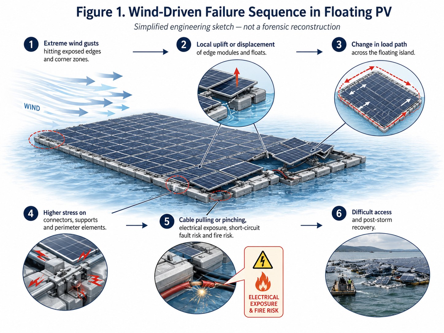
Source illustration supplied by the author. Simplified
engineering sketch; not a forensic reconstruction.
Failure
Mechanism 4: Reservoirs Are Protected, But Not Simple
Many FPV projects are installed in reservoirs because they are more
protected than open sea. Often they are. But protected does not mean
simple.
Reservoirs are not static backgrounds. Wind can accelerate through
valleys. Short, steep waves can develop over limited fetch. Water level
changes alter mooring geometry. Low water can bring a floating field
closer to banks, intake structures, shallow zones or dam equipment.
One operational reality deserves more attention: floating plants can
ground. In reservoirs with strong level variation, part of the plant or
its mooring geometry may be forced into conditions that were not obvious
at average water level. A design that looks comfortable at high water
may create slack, excessive tension, poor access or contact risk at low
water.
There is another issue becoming harder to ignore: climate-driven
water-level variability, outside historical comfort bands. Longer
drought periods, sudden inflows and unusually low reservoir levels can
push the mooring concept to its limits. This is not only a horizontal
offset problem. It is also a vertical displacement problem.
The mooring system must survive long-cycle changes in water level,
not only short storm events. Elastic systems, catenary lines, shore
anchors, deadweights, piles, hybrid layouts and clump-weight mooring
arrangements all respond differently when the reservoir moves up and
down over months or years.
A clump-weight system, for example, uses an intermediate submerged
weight on the mooring line to help manage restoring force and line
geometry. It can be useful in some configurations, but it is not magic.
If water levels move beyond the intended design envelope, the system can
still develop excessive tension, slack, poor angles or loss of effective
restraint.
The hardest condition may not be the strongest wind. It may be a less
spectacular combination: unfavourable wind direction, low water, reduced
clearance, awkward access and a plant already carrying some degradation.
Not dramatic on paper; expensive in real life.
There is also a dam-safety and environmental angle that should not be
underestimated. In reservoirs, the floating island must be kept away
from intake structures, spillways, dam equipment, sensitive banks and
environmentally protected areas. For that reason, intermediate restraint
lines or additional mooring control points may become even more
important than in open water. Their function is not only to resist
extreme loads, but to prevent the plant from drifting into zones where
contact, obstruction, debris accumulation or environmental damage could
create a much larger problem.
The practical review question is simple:
Has the plant been checked against limiting reservoir levels,
or only against a comfortable average water level?
In coastal waters, the problem changes again. Damage no longer stays
politely inside the owner boundary.
Failure
Mechanism 5: After the Storm Comes the Calm — Or Does It?
After a storm, if there is no damage, calm may return: the plant is
inspected and production is restored. But if major damage has occurred,
the calm can be misleading.
What comes next is not just repair. It can become a full marine
recovery operation.
A damaged floating PV can become a large, partially drifting marine
object that must be stabilised, accessed, isolated and recovered before
it creates a second problem.
In a reservoir, damage may mainly affect generation, equipment
recovery, owner cost and local environmental management. In coastal
waters, the same damage can create navigation risk, fisheries impact,
shoreline debris, public concern and regulatory pressure.
This is where the consequence profile changes.
A partially separated floating island may need to be secured before
repair starts. Lines may need to be cut or released in a controlled way.
Workboats may be required to hold position. Floating debris may need to
be collected before it reaches beaches, marinas, fishing grounds or
harbour approaches.
It is people working near damaged floating equipment, loaded lines,
unstable structures, energized components and moving water.
That is why recovery should be considered before the first abnormal
event. Where can the damaged section be secured? Can debris be
contained? Can crews access the area without entering an uncontrolled
structure? Can electrical risk be reduced before panels are moved,
separated or stacked?
Fire exposure also remains part of the recovery problem. If modules
have been displaced or stacked during the event, the priority is not
only mechanical cleanup. Damaged DC circuits, poor ventilation and
combustible polymeric materials may still be present when sunlight
returns.
Marine assets need marine thinking. That means emergency tow points,
recovery access, debris containment, post-storm inspection, corrosion
awareness, responsibility for removed material and a clear method for
restoring the system without increasing risk to people.
So what should be reviewed before the first abnormal event writes the
review for us?
Areas
That Deserve Stronger Emphasis in Floating PV Projects
The message is not that floating PV is too risky; it is that some
questions must be asked earlier.
1. Site-specific environmental basis
The design basis should reflect the real operating envelope of the
site, not only generic wind or wave assumptions.
The key question is not only:
What is the design wind?
It is:
Which combination of wind direction, wave action, water
level, fetch and access limitation creates the most difficult
condition?
In reservoirs, this may be low water and poor access.
In coastal waters, it may be storm damage followed by drift, debris and
recovery constraints.
2. Floating architecture and mooring philosophy
The mooring concept should match the way the floating island actually
deforms.
A membrane system, a modular float array and a framed island do not
absorb movement in the same way. The same mooring logic should not be
copied across all of them.
For large projects, scale also matters. Dividing the plant into
smaller independently moored blocks may increase cost, interfaces and
maintenance points. But it can reduce the risk of one local failure
travelling through the whole plant.
Take action, instrument your plant and validate the model.
That trade-off deserves to be made consciously, not discovered after
the first major storm.
3. Load path and weak transitions
Loads do not disappear. They move.
They move through module supports, float connections, perimeter
elements, mooring lines, anchors and cable routes. Failures often appear
where stiffness, geometry or material changes abruptly.
Those transitions should be reviewed with the same seriousness as the
main structural elements.
4. Electrical safety as a moving-layout problem
Cable routing and connector position should not be treated as
secondary details.
In floating PV, electrical components live inside a structure that
moves, deforms, ages, and may be damaged during storms. DC cables and
connectors should therefore be reviewed together with expected motion,
ventilation, access, isolation, and post-storm inspection.
A minimum level of fire detection is important for early action when
fire risk develops.
5. Recovery before the incident
A floating PV plant should not only be designed to generate power. It
should be designed to be recovered.
That means asking uncomfortable questions early:
-
Where can a damaged section be secured?
-
Can it be accessed safely?
-
Can debris be contained?
-
Can crews work without entering an uncontrolled floating
structure?
These are not theoretical details. They are the difference between a
repairable incident and a much larger marine operation.
Conclusion:
Solar Plus Marine Is Not a Simple Addition
Floating PV is growing because it solves real problems: land
scarcity, reservoir use, hybridization with hydropower, cooling benefits
and proximity to existing electrical infrastructure.
That growth should continue. But the industry should be honest about
what changes once the plant starts floating.
It becomes floating infrastructure: electrically active, mechanically
restrained, exposed to water-level variation, wind, waves, aging, access
limitations and recovery constraints.
The lesson from reported incidents is that the water adds a second
engineering discipline.
A floating PV project can look calm from the shore and still be
accumulating problems in its mooring geometry, internal connections,
cable routes, access paths or post-storm recovery plan. That is the
uncomfortable part. The asset may remain in position while the real risk
is developing somewhere less visible.
This is where naval architecture and offshore engineering can add
value by making floating PV simple and accessible.
The real contribution is asking the right questions early enough:
-
How does the island deform?
-
Where will movement be absorbed?
-
What happens if one perimeter section is damaged?
-
Can a local failure be contained?
-
Can the asset be recovered without creating a second marine
safety problem?
These are practical questions. They are also commercial questions.
Because when a project scales from a small pond installation to hundreds
of hectares of floating equipment, small assumptions become large
liabilities.
Solar plus marine is not a simple addition; it is a new engineering
interface.
Sources / References
IEA PVPS — Floating PV Report 2025. Market background, FPV growth,
O&M, reliability and technical challenges. https://iea-pvps.org/wp-content/uploads/2025/04/IEA-PVPS-T13-31-2025-REPORT-Floating-PV-Plants.pdf
World Bank / ESMAP — Floating Solar Market Report. General technical
and market background on floating solar. https://openknowledge.worldbank.org/entities/publication/9aa88b03-2eda-5793-8796-75c2990ae43f
DNV — Recommended Practice for Floating Solar PV Systems. Design,
development, operation and decommissioning of FPV systems. https://www.dnv.com/energy/standards-guidelines/dnv-rp-0584-design-development-and-operation-of-floating-solar-photovoltaic-systems/
PV Magazine — Yamakura Dam / Typhoon Faxai fire incident. Storm
damage followed by fire at Kyocera’s 13.7 MW FPV plant. https://www.pv-magazine.com/2019/09/09/japans-largest-floating-pv-plant-catches-fire-after-typhoon-faxai-impact/
Statkraft — Banja Floating Solar Plant. Project description of 2 MWp
FPV plant using PE ring pipe and membrane concept. https://www.statkraft.com/about-statkraft/where-we-operate/albania/banja-floating-solar-plant/
Offshore Energy — Banja Reservoir damage incident. Report on severe
damage to one floating solar unit. https://www.offshore-energy.biz/incident-severely-damages-floating-solar-plant-in-albania/
Times of India — Omkareshwar Dam storm damage. https://timesofindia.indiatimes.com/city/indore/storm-damages-worlds-biggest-floating-solar-plant/articleshow/109231119.cms
Taiwan News / Taipei Times — Typhoon Danas floating PV and wider
solar panel damage reports. https://www.taiwannews.com.tw/news/6150281
; https://www.taipeitimes.com/News/taiwan/archives/2025/07/20/2003840597
Scientific Reports, 2024 — Hydrodynamic Analysis of Floating
Photovoltaic Systems. https://www.nature.com/articles/s41598-024-81245-w
Allianz — Fire Hazards of Photovoltaic Systems. General PV fire risk
reference for DC cables, connectors and components. https://commercial.allianz.com/content/dam/onemarketing/commercial/commercial/pdfs-risk-advisory/ARC-Tech-Talk-Vol-8-Fire-Hazards-PV-Systems-EN.pdf
Related Reading
- Lessons Learned from Mooring Operations
- Floating Wind Turbines Transportation and Installation Engineering
Need support with floating or offshore engineering? Contact TheNavalArch.