By Alan Crowle, BSc, MSc, MScbyRes, CEng, CMarEng, FRINA, FMAREST, FSCMS
University of Exeter, College of Engineering, Renewable Energy Group
Email: ac1080@exeter.ac.uk
Introduction
The fixed steel jacket is the most common type of structure used for supporting facilities for the offshore production of oil and gas and for the support of large electrical substations. A few of these jackets have been built with sufficient buoyancy to enable them to self-float, but the vast majority have been transported from fabrication yard to offshore site aboard an ocean-going transport vessel. The installation sequence of barge-transported jackets has followed one of two paths: small jackets of relatively light weight are installed by lifting from the cargo barge using a mono-hull heavy lift vessel (HLV), whilst larger jackets up to about 12,000 tonnes use a semi-submersible crane vessel (SSCV). Jackets beyond the lifting capacities of available crane vessels have been installed by launching from transportation barges.
Development of lifted jackets
The main differences between lifted and launched jackets are that the latter have launch frames and auxiliary buoyancy tanks. Launch frames have a secondary role, serving as a supporting framework during jacket construction and for skidding the jacket onto the launch barge during load-out. Some form of auxiliary buoyancy is necessary on launched jackets to arrest the jacket during launch and as an aid during upending and installing the jacket on the seabed.
Lifted jackets require slings and trunnions, installed on the jacket, to lift the jacket from the cargo barge into the water. There are a variety of ways by which a jacket may be lifted and installed into position on the seabed. Each depends on the characteristics of the jacket.
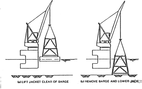
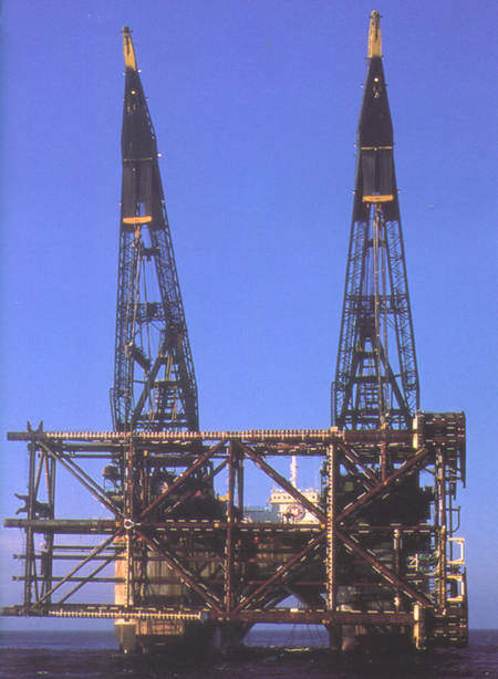
The first is the vertical lift, whereby the jacket is lifted vertically off the barge and placed on the seabed. Lifting jackets vertically is shown in Figure 1. The disadvantages are that the jacket height is limited by the available boom height capacity of the crane vessel and the vertical construction of the jacket.
In situations where the jacket is too tall for vertical lifting, it can be lifted horizontally from the transport vessel using slings attached close to the top and base of the jacket. Installation is followed by lowering the jacket base and raising the top of the jacket. This method is inappropriate for longer jackets, as the lifting capacities of the cranes reduce with increasing crane boom radius.
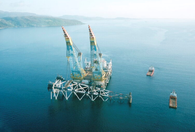
However, by using pass-over slings in conjunction with lifting points close to the jacket centre of gravity, it is possible to lift and install jackets that are not prohibitively long, as shown in Figure 2. For very long jackets, the length of the pass-over slings can be impractical. Such circumstances will probably result in a two-stage installation.
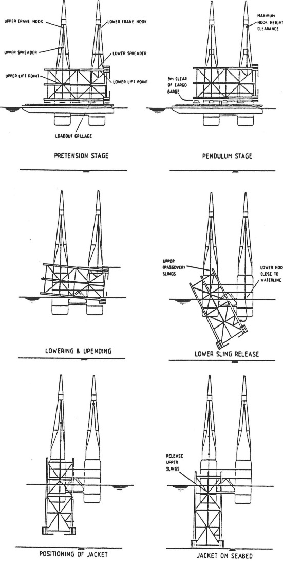
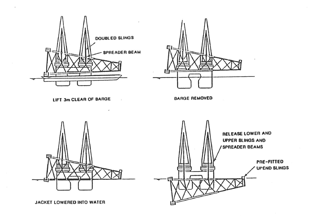
Firstly, the jacket is lifted from the transport vessel and lowered into the water until it floats, as shown in Figure 3. This requires the use of auxiliary buoyancy. The main lifting slings are then removed and the pre-rigged upending slings attached to the crane hook. The jacket is then upended and positioned on the seabed.
Conclusions
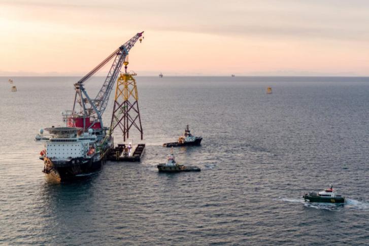
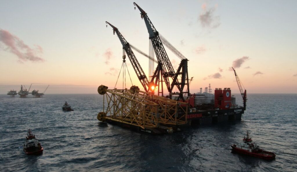
The largest lifted jacket so far is 12,050 tonnes, as shown in Figure 4. A lifted jacket is a common way of installing substructures for use in the oil and renewable energy industries.
Acknowledgements
Alan Crowle thanks his colleagues at the University of Exeter for their assistance in preparing this article and, in particular, for the assistance of Professor PR Thies.
Related reading
About the author

Alan Crowle is a Naval Architect studying for a Masters by Research at the University of Exeter. The focus of the research is into the load-out, tow out and installation of floating offshore wind turbines.
He has a BSc in naval architecture and shipbuilding from the University of Newcastle upon Tyne (1974) and MSc in engineering for marine professionals at the University of Plymouth (2020). He has over 51 years experience in the design, construction and offshore installation of marine structures. His work includes jackets, modules, FPSOs, semisubmersibles, loading buoys, LNG terminals and nearshore pipelines. He has renewable energy experience of fixed offshore wind turbines, met masts and high voltage direct current platforms. He is a fellow of RINA, IMAREST and SCMS.