Part 1 – Environment and Environmental forces
The OCIMF (Oil Companies International Marine Forum) has come out with the latest edition of mooring Equipment Guidelines (MEG) – Rev 4. This revision incorporates significant changes and updates over the MEG-3, the third Edition. The changes include, besides other additions, a guidance on documentation of mooring equipment (Mooring System Management Plan), addition of a section on human factors in mooring operations, and significant updates to the Appendix A for calculating environmental forces on tankers/gas carriers.
Mooring in the context of MEG-4 means mooring to a fixed structure like a berth, jetty, terminal or another ship.
Mooring Forces and Mooring Design

The design of mooring at berth can be broken down into a certain number of steps by thinking in very basic terms.
The problem at hand is – we are given a vessel, and we need to moor it to a berth. The first question which pops is why at all we need to berth the vessel? Why can’t we just leave it floating? Well, if we leave it floating, it is subject to environmental elements of wind, current, waves, tides etc. These will make it drift, with the possibility of hitting another vessel in the vicinity.
The next thought that comes is: what’s the best way to secure it to a berth? The simplest solution we can imagine is using ropes to tie it to strong and fixed structures on the berth. A ship needs equipment like bollards, fairleads and winches which can help secure the rope from ship to the mooring equipment on the berth.
So, how do we go about selecting the right sized rope? What about the bollards, fairleads and winches on the vessel? How big should they be? It is natural to expect that a bigger ship will require bigger sized equipment (bollard, winches, fairleads etc.) and ropes to secure it. How could we devise a method to do it?
In simplest terms, mooring involves tying the vessel to a berth using ropes so that the vessel stays in place and is not carried away by the environment. The environment may comprise wind, current, tides, waves, ice, swell etc. which the berth is subject to.
To know how many and how big ropes and what size equipment are needed, we should have an estimate of how much environmental forces the vessel is subject to. Once we know the forces, we can go about tying ropes in such a way that these are able to resist the forces.
Hence, the steps to designing a mooring system can be:
- Step 1: Get the environmental data for the berth – wind, wave, current, tide etc.
- Step 2: Calculate, based on the size and geometry of the vessel, the total environmental forces on the vessel
- Step 3: Design a mooring system comprising ropes and equipment adequate for resisting the environmental forces obtained in Step 2. This includes designing the mooring pattern and selecting the right equipment.
In this article we’ll look into Steps 1 and 2, while the Step 3 will be dealt with in Part 2.
Step 1 – Environmental data
The application of environmental data depends on the purpose which we’re using it. If we’re designing the mooring equipment of a specific berth or terminal, then the environment experienced at that specific berth is important. This is obtained from Metocean data for the specific berth location.
However, things are different if we’re designing the mooring equipment for a ship (which is what this article talks about). A ship may visit multiple berths over its lifetime, and each berth may be subject to different environments. Does that mean that we gather the environmental data of each berth the ship is expected to visit over its lifetime, and then take the worst-case environment? Such an exercise will be extremely cumbersome.
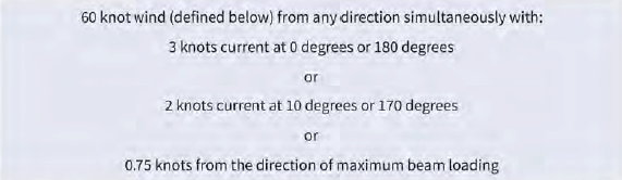
MEG-4 provides a simple solution: Section 3 of MEG-4 provides the ‘Standard’ environmental criteria which are to be used for ships. These criteria cover a wide range of environmental conditions and can be used for the mooring design. However, these are applicable only for vessels with DWT 16000 MT and above. The criteria are shown below:
Loading Conditions and tidal variations
The ship may be loaded to different drafts, which leads to different windage and current areas. For example, when the vessel is ballasted, it has a higher windage area and so the wind forces are expected to be higher compared to other loading conditions with higher draft. Similarly, fully loaded condition with fetch higher current forces compared to other loading conditions.
For the purpose of mooring design, it is generally recommended to investigate two extreme conditions:
- Fully loaded condition at lowest astronomical tide (LAT)
- Ballasted condition at highest astronomical tide (HAT)
Water Depth to Draft Ratio
The ratio of Water Depth (WD) to Draft (T) is a critical parameter affecting the current forces on a vessel. OCIMF recommends the following values to be used for the WD/T ratio:
- For tankers, WD/T to be taken as 1.05 when loaded and 3.0 when in ballast condition
- For a gas carrier the WD/T should be taken as 1.05 for all conditions
We can see here that there will be multiple cases for which the forces have to be calculated.
Since the wind of 60 knots can be from any direction, simultaneously with current from either head/following seas or beam seas, we need to investigate all cases while varying the direction of current from 0 to 360 deg, and also varying the loading condition (ballast/loaded). To simplify, we can create cases by considering wind and current to be collinear (along the same direction), and investigate the cases listed below:
The cases are listed below:
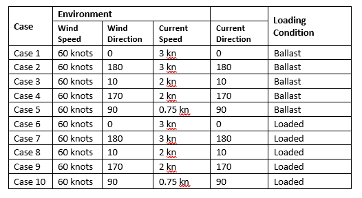
Now that we have defined the environmental conditions – wind and current, which also included the loading conditions and water depth to draft ratio, we can move on to the next step: calculation of environmental forces.
Step 2 – Environmental forces
At a berth, generally it is only wind and current forces which significantly impact the design of moorings.
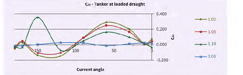
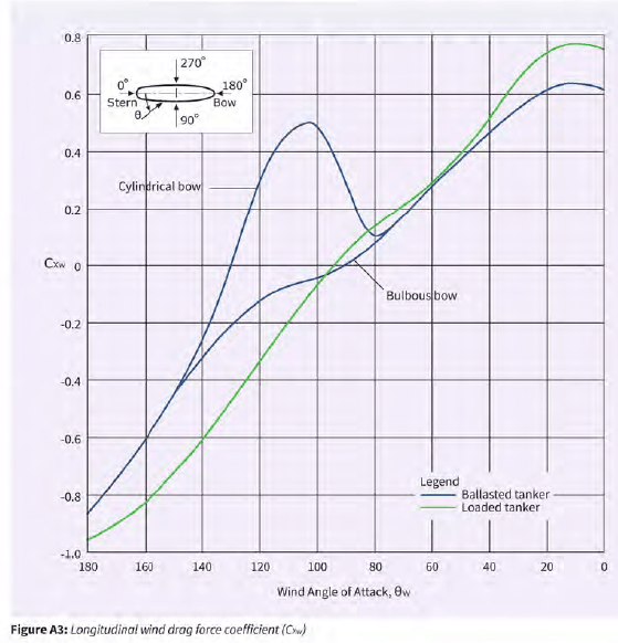
The environmental forces on the vessel can be calculated using the force coefficients provided in Appendix A of OCIMF MEG-4. These tables provide the coefficients for Wind and Current forces depending on the vessel heading, loading condition (ballasted/loaded) and also the Water Depth to Draft ratio. At this stage, and for the purpose of this article, waves and other factors which are ‘dynamic’ in nature (i.e., which cause time-varying forces on the ship) are not considered, and the analysis is limited to a ‘static’ analysis.
The environmental force coefficients comprise the following:
- Surge force or longitudinal force – wind and current forces faced by the fore or aft of the vessel
- Sway force or transverse force – wind and current forces faced by the beam of the vessel
- Yaw moment – wind and current yaw moment which makes the vessel turn about its vertical axis
The force coefficients provided in MEG-4 follow a specific sign-convention as per the figure below:
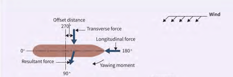
The coefficients can be obtained from the charts and tables provided in Appendix A of OCIMF MEG-4.
Next, we calculate, for all cases listed in Step 1, the environmental forces of wind and current (forces and moments).
The forces are obtained from the coefficients by using the standard formulae:
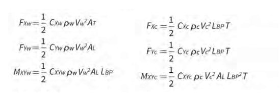
Once we have the environmental forces, the next step is to design/select the mooring equipment based on the forces obtained.
Mooring equipment can be the following:
- Mooring lines and shackles
- Bollards
- Fairleads
- Winches
Each mooring equipment is specified by its Safe Working Load (SWL), which is what we need to determine.
OCIMF provides a simple approach to calculating the SWL once environmental forces are calculated.
OCIMF proposes calculation of a parameter called the ‘Ship’s Design MBL’.
In Part 2, we’ll look into what is Ship’s Design MBL, and also how the mooring pattern for the vessel can be designed.
Disclaimer:
The views, information, or opinions expressed in this article are solely those of the author and do not necessarily represent those of TheNavalArch Pte Ltd and its employees

Prem Shankar
Founder
The author is the founder of www.thenavalarch.com, a website providing useful low-cost software and other online resources for Naval Architects. A graduate in Naval Architecture from Indian Institute of Technology (IIT), Kharagpur, he has worked on the design, engineering, construction and installation of a variety of marine and offshore structures, ranging from ships to offshore platforms and FPSO’s. TheNavalArch is part of his endeavour to bring rich and low-cost online content for the oil & gas and marine communities. The author can be contacted at info@thenavalarch.com
-
Bollard Pull Calculations for Barge
$49.00 Add To Cart -
ShipSafe – Trim and Stability Calculator
$499.00 Add To Cart -
Mooring Forces Calculator (Port or Stbd on Quay)
$99.00 Add To Cart -

Pad-Eye Design Spreadsheet
$49.00 Add To Cart -
Bollard Pull Calculations for Ships
$79.00 Add To Cart -
Pipe Stacking Height Calculator (Bare Steel Pipes)
$39.00 Add To Cart -
Cargo Forces & Accelerations – Open Ocean
$49.00 Add To Cart -
Spreader Beam Design Spreadsheet
$99.00 Add To Cart -

Towing Bridle Design Spreadsheet
$39.00 Add To Cart -
Ship Resistance Calculator (Holtrop & Mennen)
$99.00 Add To Cart -
OCIMF Environment Forces Calculator – Tankers (Updated toMEG-4)
$99.00 Add To Cart -
Mooring Line Catenary App
$99.00 Add To Cart

Thanks for this insightful article. I’m looking forward to part 2.
I was wondering what the relative effect of waves (wind waves / passing ships) is on the mooring forces. Do the regulations provide for an assessment method for these effects?
Really useful information, this calculations are to be done for vessels above 16000MT DWT but what about mooring arrangement for a barge with less DWT?