Description
PRODUCT UNDER REVIEW, TO BE LAUNCHED SOON
What does this Excel App do?
This Excel sheet helps you design the berth mooring of a Tanker based on OCIMF Mooring Equipment Guidelines 4th Ed Appendix A (MEG 4)
It calculates the wind and current force and moment coefficients from OCIMF, and calculates final line tensions from these coefficients
This spreadsheet can be used for smaller ships approximately 16000 MT Deadweight to big VLCC’s of upto 500000 MT Deadweight
The mooring line pattern can be input in the calculator and line forces on the mooring lines are the outputs
How to use this Excel App
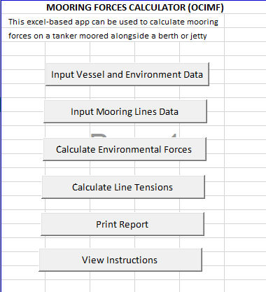
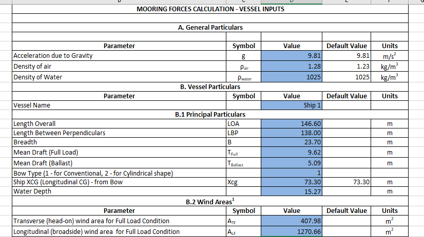
The user is asked for some inputs for the Vessel, Environment and the Mooring Lines. The Input cells are highlighted in blue.
The user can select the default environment stated in OCIMF as the environment, or define multiple environment cases depending on site data
The user has to provide all the inputs highlighted in blue. Please do not make any changes to the output sheets
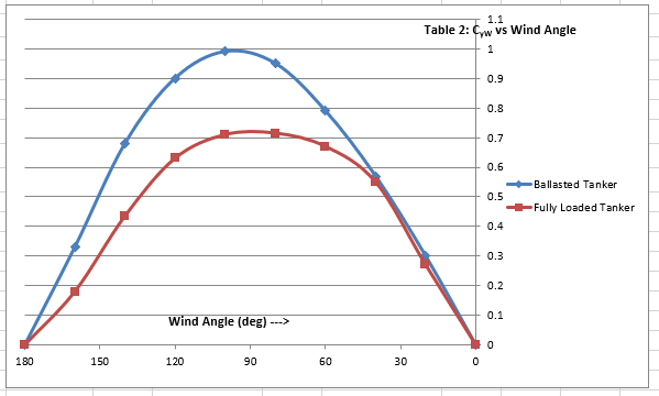
For some inputs, Tables and charts are required to be referred. These Tables and charts are provided along with for the user to enter these inputs.
Once all inputs are provided, the coefficients for current and wind forces are calculated from charts provided in Appendix A, and mooring forces too are calculated
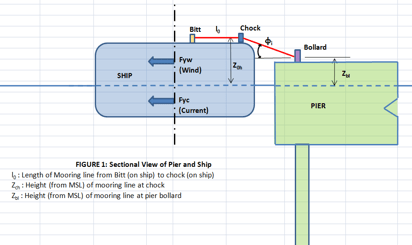
Coordinate System and Axes (See figure on right)
The origin of coordinate system is at fwd end of the vessel longitudinally, Centreline transversely and at Mean Sea Level vertically
X-axis is positive towards fwd, Y-axis is positive towards port, Z-axis is positive vertically upwards, Anti-clockwise Yaw moment is positive
Clarifications/Assumptions/Limitations
1. DWT Range of Tankers: 16000 to 500000
2. Wind and current forces are assumed to be steady state in nature. Wave force is assumed to be negligible
3. TRIM
For wind coefficients, trim is assumed to be zero for fully loaded condition, and 0.8 degree for ballast condition. For trim significantly varying from these values, the outputs will need correction
For current coefficients, trim is assumed to be zero for both fully loaded and ballast conditions. For trim significantly varying from these values, the outputs will need correction
4. L/B Ratio
The L/B Ratio is a minimum of 5.5
5. Water Depth to Draft Ratio (WD/T Ratio)
Not valid for Water Depth to Draft ratio (WD/T Ratio) less than 1.05 for ballasted tanker, and 1.02 for loaded tanker
For WD/T ratio greater than the upper limit, the values for upper limit are used. For example, for loaded tanker with WD/T = 7, the Cxc/Cxyc values for WD/T = 3 and Cyc values for WD/T = 6 are used
6. Angle of Attack
For angles of Wind/Current attack between 180 and 360 degrees, force/moment coefficients are as follows
Longitudinal Force: Same magnitude and sign as that for equivalent angle between 0 and 180 degrees
Transverse Force: Same magnitude but opposite sign as that for equivalent angle between 0 and 180 degrees
Yaw moment : Same magnitude but opposite sign as that for equivalent angle between 0 and 180 degrees
References
1. OCIMF Mooring Equipment Guidelines 4th Ed
2. DDS-582 US Navy Calculations for Mooring Systems


Reviews
There are no reviews yet