Description
INTRODUCTION
Nearshore pull-in operation (or Landfall pull-in operation) is one of the most essential operations during the cable lay and pipelay operations. This operation is critical to the entire project because the section of the cable connects the output from the offshore assets to the land units. There are several factors that can lead to excessive cable loads. That’s why various contributors to the load must be analyzed. The sheet apprises the user various contributors of loads that the tensioner and cable would sustain.
WHO SHOULD USE THIS?
This sheet can be typically used by:
1 Project engineers (nearshore) and tender engineers in installation contractors
2 Tensioner / winch designers
3 Pull-in route planners
4 Structural engineers for foundation loads
5 Geotechnical engineers for soil bearing capacity estimation
6 Cable designers/specialists
THEORY
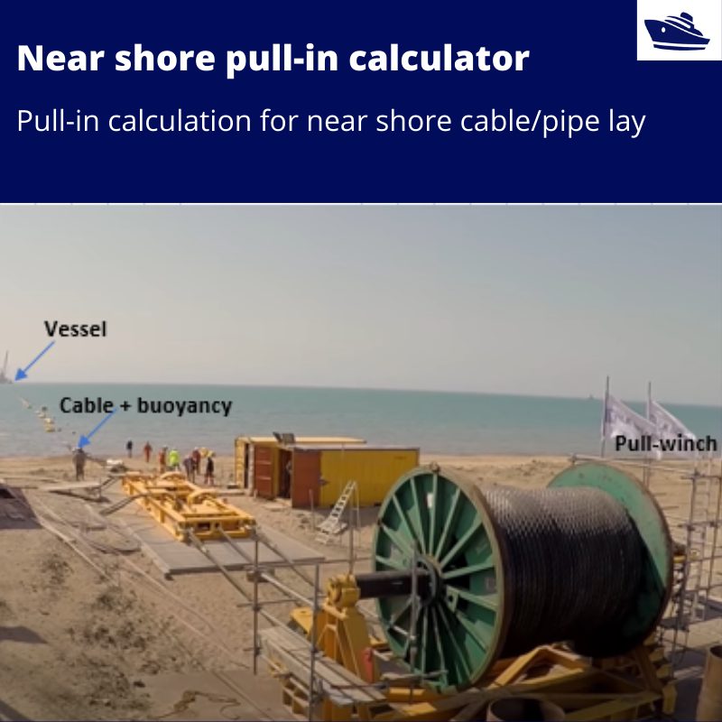
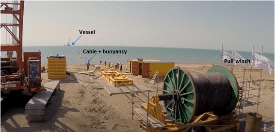
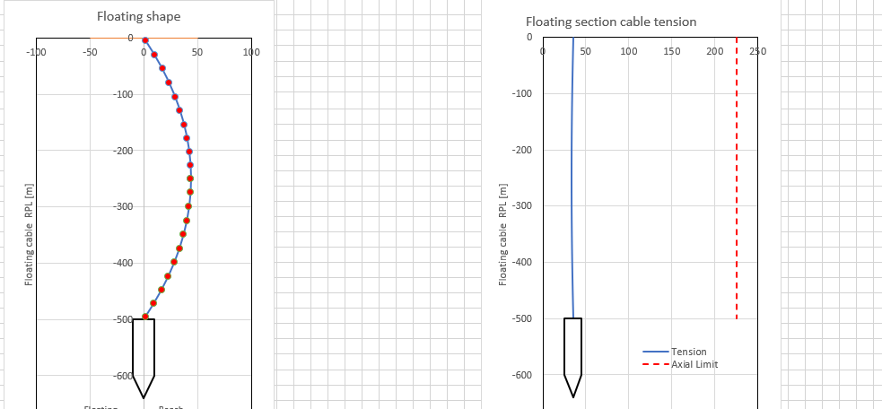
The cable is usually paid out from a vessel moored at a distance from the shore. To reduce the force due to friction, the cable is floated using buoyancy units.
Since it is a time-consuming process, the cable encounters cross current along the path which leads to a lateral catenary formation due to drag forces.
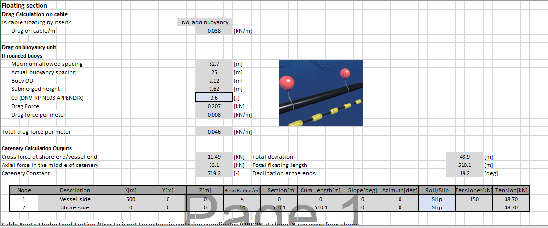
The loads are calculated using catenary formulations. The load is maximum at the ends and has a direct impact on tensioner loads on both vessel and shore side.
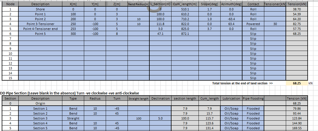
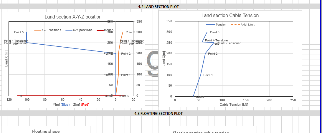
For the section on land, the catenary formations are replaced by direct line friction. The source of friction is due to rollers/sliders along the path. There can be route bends using quadrants
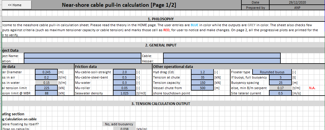
Also, there can be tensioners/winches along the path to reduce the cable line loads. The tension aggregation over length is based on the capstan/sheave function. The sheet allows the friction coefficients to be changed as per user experience. A total of 10 maneuvering points can be used in the sheet. User to implement judgment to simplify within the range.
Thirdly, sometimes the cable is pulled all the way to a point on land via a horizontal direct drilling duct (HDD). To reduce tension, the duct may be flooded or it may be lubricated
In the absence of lubrication, the dry conditions prevail. The HDD shape parameters may be adjusted. A total of 10 sections can be used in the sheet. The formulae are again based on sheave friction
More discussion on the topic in DNVGL-RP-0360
RESULTS
1 Expected tension at the end of the cable route
2 Tensioner sizing and setting
3 Buoyancy unit selection
4 Route optimization
5 HDD bend optimization (rarely required)
ASSUMPTIONS / CONSIDERATIONS
1 Since the operation is performed at a slow speed with multiple intermittent pauses, the calculation is presented in STATIC mode
2 The analysis is based on cable fully pulled to the end of the operation. This phase is when the entire cable is exposed to the external loads. For the design of tensioners, quadrants etc
ths force is useful.
3 The floatations are equally spaced along the path and are all equal.
4 The influence of bend stiffness is assumed negligible. The quadrants along the path have high bend radius.
5 Any shape other than round or cylindrical shapes can be replicated by using equivalent outer diameter. The drag coefficient can be adjusted.



Reviews
There are no reviews yet