In my working with the marine transportation industry for more than a decade now, I have come across many different calculations for required bollard pull for both barges and ships. The principles of the calculation are same, whether it is a ship, a barge or any other structure being towed (e.g., a rig). The environmental forces of wind, wave and current on the structure need to be calculated, added up, and factored for the towing efficiency to obtain the required bollard pull to tow the vessel.
Going by the above methodology, it would appear that there should be no difference in the calculations for Barge or Ship. However, this is a common mistake which may lead to selection of a tug which is either unfit or oversized for the vessel selected.
The simplest way to illustrate the differences is to breakdown the calculation steps of bollard pull and analyze them. The calculation steps for Bollard Pull are detailed below:
- Step 1: Calculate the forces of the environment acting on the vessel. These forces are: Current, Wind and Wave
- Step 2: Factor the environmental force for the towing efficiency to get the required bollard pull for towing the vessel.
The differences between a ship and a barge lie in the methods applied for calculating the environmental forces (Step 1).
Wind Force:
The wind force acts on the structure above the waterline of the vessel. The formula for wind force calculation is straight forward, and it is the same for any vessel – whether Barge or a Ship. The force is calculated as Pressure x Area, where Area is the projected area of the vessel exposed to the wind.
The projected area will comprise of the area of the hull above the water plus the area of superstructure/Cargo
In case of Barge, generally superstructure is non-existent or minimal, and cargo is the contributor to windage area. However, in case of ships, there can be both cargo and superstructure which contribute to the windage area. Generally, if the cargo and superstructure are located quite apart along the length of the vessel, then it is advisable to consider full windage area of both in calculations. However, if one is shielded by other (say, if the superstructure in aft is shielded from wind by Cargo located just forward of superstructure), then a shielding factor can be applied to reduce the contribution of the shielded structure. For more on shielding factors, please see DNVGL-RP-C205 (Aug 2017), 5.3.3 Shielding Effects.
Current Force:
Current force refers to the ‘drag’ force which the underwater body of the vessel experiences. This is caused by the ‘relative’ flow of current against the body of the vessel. The drag depends on the underwater geometry of the vessel.
A Barge is generally a flat, box-type structure. Its bow can be flat, raked or spoon-shaped. Flat structures will attract more drag compared to a more streamlined structure like a ship-shaped vessel. A flat bow also attracts more drag than a raked or curved bow. For a ship, the body is much more streamlined than the barge. Further, if the bow is a bulbous bow, it helps in reducing the drag.
Thus, for the same dimensions, the Barge is expected to attract more drag compared to a conventional ship-shaped vessel. Generally, the calculations for a Barge a more straightforward, based on the Morison equation
F = ½ ρ x V
2 x C
d x Projected Area
The term ½ ρ x V
2 is the pressure created by water on the surface of the vessel. Projected area is the sectional area of the vessel perpendicular to the direction of flow. If the current direction is along the length of the vessel, then the midship sectional area is the area to be used.
The term C
d is called the drag coefficient. This term is of huge significance, and it is this term which determines how the geometry of the body will affect the drag force. For a relatively flat body like a barge, C
d is expected to be higher, while for a streamlined body like a ship, C
d will be much lower.
For most barges which are flat faced, a conservative value for C
d can be taken to be 1.0 (which is the value our Bollard Pull calculator also uses). For barges of other shapes, an established method like one described in OTC 3320 paper may be used.
For ships, the calculation of Cd is more complicated, and while it is also principally based on Morison equation, the calculation has to be more elaborate and take into account its geometric differences.
A method like ‘Holtrop-Mennen’ can be used to calculate the ‘Calm Water Resistance’ of the ship, which is the resistance which it experiences due only to current (with no waves). The resistance includes terms like
- Frictional resistance
- Appendage Resistance
- Wave making resistance
- Bulbous bow resistance
- Transom resistance
We can see that in case of a ship, the calculation is more elaborate and pertains to special geometrical considerations. In effect, for a barge of similar size, the current force on a ship may be lesser due to its streamlined shape.
Added Wave Resistance:
As the vessel moves forward, these oncoming waves interact with the vessel’s body to create resistance forces called ‘Added Wave Resistance’. These are external forces created purely by the action of the sea against the vessel and are dictated by the height of the waves the vessel encounters.
The effect they have on the vessel will be affected by the geometry of the vessel. Something which we can infer is that a geometry with gentler and more streamlined shape will attract less resistance compared to a flat geometry. A Barge is generally box-shaped and has more flat surfaces compared to a ship which has gentler shape and more curves. Thus, the added wave resistance too is expected to be lower for a ship compared to a barge. This is evident is the formulae which are used for calculating the added wave resistance. The DNV-RP-H-103 provides a formula for estimating the added wave resistance based on the width of the vessel, wave height and shape of the bow. The formula is reproduced below from Section 7.2.6.4 of DNV-RP-H-103
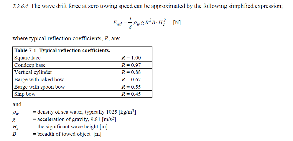
We can see that the reflection coefficient (R) is the distinguishing feature which depends on the shape of the bow of the vessel. Obviously, for a ship shaped bow, the Reflection coefficient is much less. Compared to a square face vessel of same breadth in the same wave height, a ship shaped bow is expected to encounter only around 20% of the wave resistance on the square face.
Conclusion:
Thus, we see that the approach to calculation of Bollard Pull for a ship and barge have marked differences due to the differences in their geometrical shapes. If the simplifications which are used for Barges (e.g., using a current drag coefficient of 1.0) are used on ships without any critical evaluation of the ship’s geometry, the resulting bollard pull can be highly overestimated, leading to the selection of a much oversized tug than necessary to tow the ship and subsequent high costs of towing. High savings can be ensured by taking time to study the ship’s geometry and doing a bollard pull calculation which accounts for its geometry and follows the appropriate methods for estimation of environmental forces.
Disclaimer: This post is not meant to be an authoritative writing on the topic presented. thenavalarch bears no responsibility for any incidents or losses arising due to the use of the information in this article in any operation. It is recommended to seek professional advice before executing any activity which draws on information mentioned in this post. All the figures, drawings and pictures are property of thenavalarch except where indicated, and may not be copied or distributed without permission.


This is a worthwhile explanation that will assist all those who are involved with the towing of ships and barges. The differences in existence are clearly pointed out. I hope that the author, in the near future, will provide a more involved revision on this subject, as this will be of benefit to all Naval Architects.
With kind regards,
Eur Ing Harry Alexander Karanassos, CEng, FRINA
Hi Harry
Many thanks for your feedback. We will continue to delve deeper into related topics. Thanks for your support