By Alan Crowle, BSc, MSc, MScbyRes, CEng, CMarEng, FRINA, FMAREST,
FSCMS
University of Exeter, College of Engineering, Renewable Energy
Group
Email ac1080@exeter.ac.uk
Introduction
This article investigates the marine design aspects of large offshore
modules for use in the oil and gas industry and for offshore electrical
substations. Lifted modules and float-over modules are included in the
article. The advantages and disadvantages of different load-out methods
by trailer, skidding or lifting are discussed. Transportation on cargo
barges and on self-propelled heavy transport vessels are compared. The
lifting of modules is restricted by available crane capacity, and for
floatover, the limitations are the transport vessel. However, these
operations are sensitive to weather criteria which has consequences for
the offshore installation scheduling. Maximum lift weights are presented
for high-volume living quarter modules and very compact process modules.
The key to maximizing the lift capacity is to minimize the lifting
radius and ensure that the lift points are placed in the optimum
position with respect to the package centre of gravity. The lift radius
is minimized by ensuring that all major layout decisions incorporate the
needs of module installation. Float-over installation requirements are
considered for fixed and floating structures. The requirements for
ballasting, mooring and fenders are discussed. The accuracy of the
overall weight estimate is also important in maximizing the module
lift/installation weight.
History of Installing Large Items
During the age of
sail, the sheer
hulk was used extensively as a floating crane for tasks that
required heavy lift, Figure 1. At the time, the heaviest single
components of ships were the main masts, and sheer hulks were essential
for removing and replacing them, but they were also used for other
purposes. Sheers are spars lashed together and raised up an apparatus
for hoisting heavy weights, generally known as sheerlegs. These consist
of two or more upright spars meeting at the top, where the hoisting
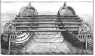
tackle is placed, and set wide apart at the bottom. Old ships were
joined together into a catamaran for salvage work, see Figure 2.
Figure 1 Sheer Hulk (Credit UK National Maritime Museum)
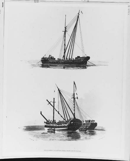
Figure 2 Catamaran used for salvage (Credit UK National Maritime
Museum)
The concept of float-over is not new; it extends back to an original
idea for the installation of bridges where bridge spans were floated in
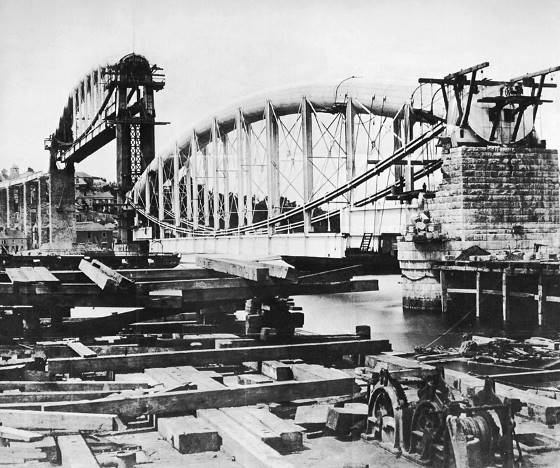
between pillars on barges and then lowered by ballasting. Brunel used
the float-over method to install the main bridge spans of the Royal
Albert Saltash Bridge between Devon and Cornwall, in the UK, figure 3,
in 1854. Two pontoons with sealed hulls were constructed and floated
into docks excavated below each end of the truss. Valves were opened and
the pontoons flooded until they came to rest on the dock bottom. A
timber frame was built on each pontoon capable of supporting the weight
of the truss. At low tide valves were opened to drain the water from the
pontoons. As the tide came in, the pontoons floated, lifting the truss.
It was slowly towed into the middle of the river and swung round 90°.
The truss was edged into position between the centre and western pier
and the pontoon valves opened, allowing the pontoons to go to a deeper
draft and the truss to settle onto the piers.
Figure 3 Floating transfer of Bridge Section (Credit Cornwall
Museum)
Types of substructures at offshore locations for float-over
-
Fixed platform
-
SPAR
Types of substructures at inshore locations for float-over
-
SPAR
-
Tension Leg Platform
-
Semi-submersible
-
Gravity-based structure with multiple legs.
-
Gravity-based structure, single column.
Crane Vessels
There has been a constant drive to minimize offshore work and
construct as much as possible onshore. Onshore construction costs less
than working offshore. Onshore construction is not affected by wave and
current action. The use of larger modules reduces offshore hook-up
requirements.
Crane vessels are specialized ships used in lifting heavy loads. The
largest crane vessels are used for offshore construction. Conventional
mono-hulls are used, but the largest crane vessels are semi-submersible
types as they have increased stability and reduced motions in waves. On
a sheer leg crane vessel, the crane is fixed and cannot rotate, and the
vessel therefore is maneuvered to place loads.
In the 1940s, derrick barges were built, with a 150-tonne revolving
crane. The arrival of this type of vessel changed the direction of the
offshore
construction industry. Constructing oil platforms could
be built onshore as modules, prior to transport and offshore
installation.
In the 1960s, ship-shaped crane vessels were developed from the hulls
of converted tankers, with a capacity of 300 tonnes. This type of crane
vessel was better adapted to the harsh environment of the North Sea. Soon after
that, with the commissioning of additional ship-shaped crane vessels,
lift capacity went up to 3,000 tonnes. The use of crane vessels with
such lifting capacities made it possible to build fewer but heavier
modules, providing an enormous financial advantage to oil companies, as
it drastically reduced the volume and duration of offshore hook-up work.
Oil and gas fields could now produce first-oil faster.
Crane vessels operating in the North Sea were still quite sensitive
to wave action, and this made operations during the winter months
virtually impossible. To increase heavy-lift capacity and operability in
the North Sea waters, the application of the semi-submersible principle
for heavy-lift crane vessels led to increased lift capacity and
crucially, to improved work operability.
When large gravity base structures were developed the installation of
large single piece modules was done by inshore float-overs. Later in
benign sea-states float-overs have been carried out at offshore
locations.
Heavy Lift Crane Vessels
In reviewing crane capacity, the following needs to be considered
-
Convert all lift capacities to a common system of units i.e.
(metric) tonnes -
Minimum draft for lifting
-
Intact stability during lifting
-
Distance of cranes from the edge of the crane vessel
-
If Dynamic Positioning (DP) is used there are limitations on how
close the crane vessel can be to structure -
Some cranes may be able to be tied down to increase capacity, in
the non-rotating mode -
Chart showing reduction in capacity against radius
-
Chart showing maximum allowable hook height against crane
radius -
Capacity for auxiliary hooks
-
Lift module off a cargo barge or a heavy transport vessel onto
the sub-structure -
Lift smaller modules onto the main deck of the crane vessel at an
inshore location
When comparing crane vessels of similar capacity those with longer
crane booms can lift taller modules. Thus, crane vessels with a long
crane boom are well suited to lift accommodation modules, which are tall
and have low weight-to-volume ratios. Whilst process modules, which are
compact and have high weight to volume ratios are well suited to crane
vessels with shorter crane booms.
Table 1 Typical Large Crane Vessels
| CRANE VESSEL | NUMBER OF CRANES | NOMINAL CAPACITY | HULL TYPE |
|---|---|---|---|
| SLEIPNIR | 2 | 20,000 | SEMI SUBMERSIBLE |
| THIALF | 2 | 14,200 | SEMI SUBMERSIBLE |
| S7000 | 2 | 14,000 | SEMI SUBMERSIBLE |
| BALDER | 2 | 6, 945 | SEMI SUBMERSIBLE |
| AEGIR | 1 | 4,000 | MONOHULL |
| SEVEN BOREALIS | 1 | 5,000 | MONOHULL |
| SUBSEA7 STRASHNOV | 1 | 5,000 | MONOHULL |
| STANISLAV YUDIN | 1 | 2,500 | MONOHULL |
Types of Modules
Lifted Module Installation
Sheer leg crane vessels are not generally used for offshore lifting,
because of poor motion characteristics and hence downtime in bad
weather.
Single rotating crane vessels are commonly used around the world. All
of them have multiple mooring points and a few have Dynamic Positioning.
Dual crane vessel offers the largest range of lifting capabilities.
Load-out
Lifted load-out is limited by onshore cranes or by harbour sheer legs
vessels. The use of self-propelled modular transporters (SPMT) is a
standard method of loading out modules of up to 13,000t, where this
weight includes module, rigging and load-out grillage. Skidding is no
limits
Design Considerations
The modules will be designed for the ‘Not-to-exceed’ Weights for the
Load-out, Sea Transport, and Lift conditions. The Not-To-Exceed (NTE)
lift weights are the module weights only; they do not include for the
weights of grillages and rigging but do include for installation aids
such as rigging platforms, bumpers, and guides. The Not-To-Exceed (NTE)
load-out and transport weights include the weights of rigging, Figure 4,
installation aids such as rigging platforms, bumpers, and guides.
Figure 5 show a module just after lift off the transportation
vessel.
The assumed load-out arrangement should consider the local barge
capacities, trailer axle capacities, construction support conditions and
barge grillages/sea-fastening. The trailers will be aligned parallel to
the longitudinal axis of the module (and barge). The trailers will bear
on the underside of the load-out grillage, if required, or otherwise on
the underside of the bottom-level plate girders. The load distribution
should reflect the module NTE weight and centre of gravity envelope. No
uplift should be permitted.
In the trailered load-out analysis the land slipway/foundation
stiffness and barge stiffness will not be simulated, as any out-of-level
will be accommodated by the stroke of the load-out trailers
Transportation Loads depends on transport vessel type, distance of
voyage, fabrication facility quay strength and water depth, speed of
travel and hence duration of voyage. Motions and deflections are
calculated for the expected sea states.
For a SPMT load-out a lower grillage arrangement is required to
transfer loads into the web frames and the bulkheads of the transport
vessel. With a skidded load-out the skid rails transmit the load-out and
transportation loads into the hull of the transport vessel.
Sea-fastenings can connect the module directly to the deck of the
transport vessel and thus has the advantage of spreading loads into the
module and hence minimising module weight. However, to minimise offshore
cutting time for sea-fastenings a system of roll and pitch stops at the
main module nodes is used This requires heave straps which are connected
onto the upper load-out grillage (or skid shoes) or directly onto the
transport vessel deck. Only the heave straps are cut prior to
lifting.
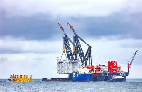
Lifting with a large semi submersible crane vessel is shown in
Figures 6 and 7
Figure 4 Lift node, sling retainers in red, slings (Credit
Saipem)
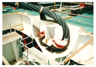
Figure 5 Module lift off from heavy transport vessel (Credit
Saipem)
Shows upper and lower grillage and docking cone
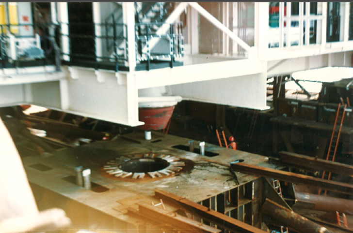
Figure 5 Module Lifting (Credit Saipem)
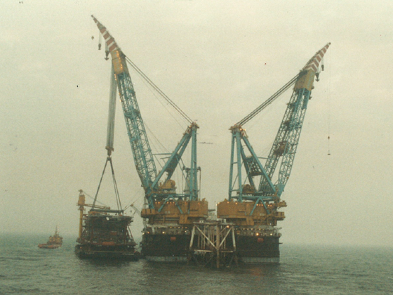
Figure 6 SSCV Lifting substation from HTV (credit Heerema)
Float-over Vessels
Intact stability is dependent on ballast capacity, intact stability
and barge shape
Motions depend on combined inertia of cargo, ballast and vessel, the
natural roll period and the wave height and
wave period and relative wave direction
Other issue to be checked are global strength, local strength,
fatigue and slam on overhanging modules.
Float-overs have been performed by using launch barges or heavy
transport vessels. Some launch barges have been modified to carry larger
loads by adding sponsons at one end.
Offshore module installations can be performed by lowering
fully-integrated module units onto pre-installed jackets by means of
float-over operations with heavy transport vessels (HTV) . The benefits
of using HTVs for float-over installations include:
-
High capacity ballasting systems compared to cargo barge
-
More rapid transit from the fabrication yard to final
location -
No need for setting up offshore mooring with anchors
-
Much quicker than a barge
Float-over Operation
While this basic principle of load-out and transportation remains the
same, as for lifting, methods and systems used to execute the concept
vary significantly and pose numerous technical and operational
challenges.
Figure 7 T barge floatover with Module for fixed structure (credit
Heerema)
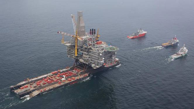
From an operational point of view, there are several distinct
phases:
-
Standby – The vessel is a safe distance from the sub-structure
but connected to the mooring system, -
Docking – The vessel enters the sub-structure,
-
Pre-Mating – It is critical that the vessel motions be limited to
suit the chosen shock absorber geometry. -
Mating – The module is lowered onto the sub-structure by either
rapid ballasting of the vessel -
Post-mating – A gap is created between the module and the
float-over vessel -
Exit – The float-over vessel is removed from the slot.
Floatover types are shown below:
Figure 8 T barge onto a (floating) semi submersible hull
Figure 9 T barge floatover onto a fixed structure
Figure 10 Dynamic Positioning Heavy Transport Vessel onto a fixed
structure
Figure 11 Catamaran floating onto a (floating) spar hull
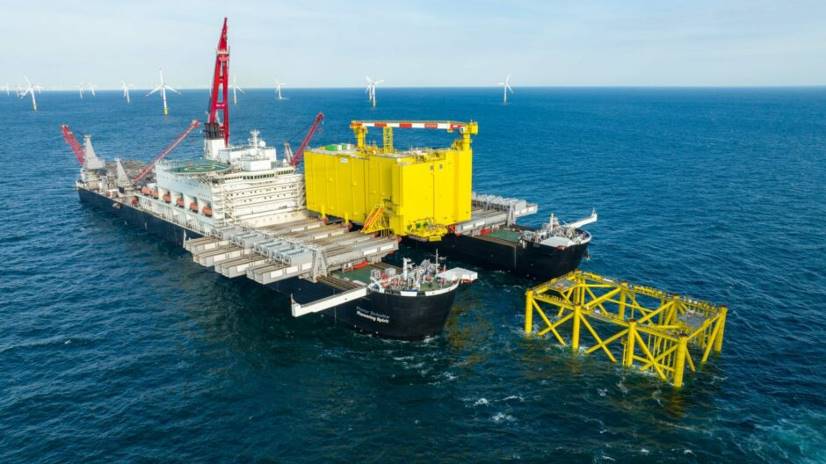
Figure 12 Dynamic postioned catamaran onto a fixed substructure
Figure 8 Floatover by T barge onto semi-submersible hull (Credit
McDermott)
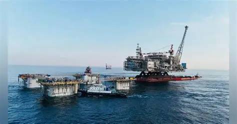
Figure 9 T barge floatover over fixed structure (credit CGTN)
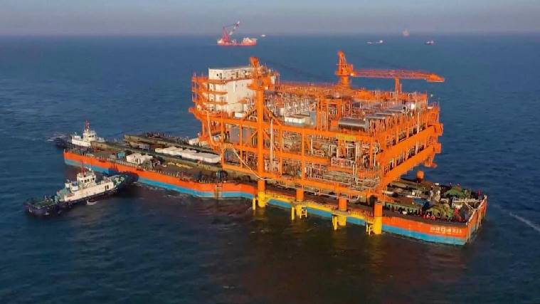
Figure 10 DP HTV direct floatover (credit Cosco)
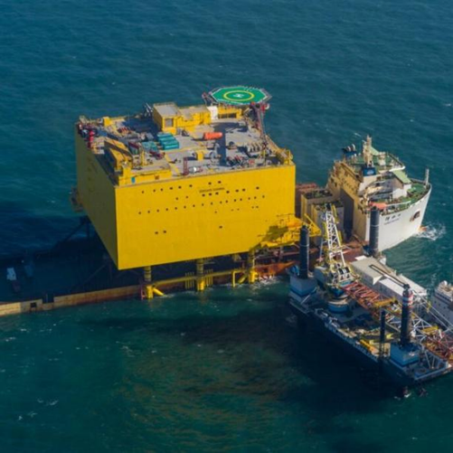
Figure 11 Dual HTV floatover onto a floating Spar (Credit
Equinor)
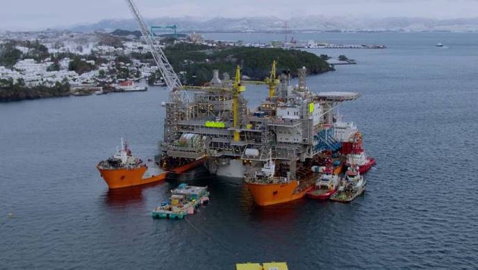
Figure 12 DP Catamaran installing substation (credit Allseas)
The float-over vessel is critical for a successful float-over
operation. This float-over vessel will be used to load out the module,
transport it to site safely, perform the float over, and return.
Although there are a number of self-propelled vessels used in float-over
operations, many are accomplished using cargo barges. In some cases,
multiple vessels in catamaran or trimaran configuration have been used,
for inshore float-overs.
The float-over vessel must be narrow enough to fit inside the
sub-structure legs but have enough strength and stability to load out
and transport the module. The float-over vessel also needs enough
strength and stability to load out and transport the heavy module, which
usually requires a wider float-over vessel.
The use of hydraulic jacks allows the module to be towed to site on
the float-over vessel at a low level and raised to float-over elevation
just prior to the float-over operations. This can be critical for module
with a high vertical center of gravity, where stability during the tow
is marginal or unacceptable. The hydraulic jack system also provides
speedy lowering of the module. However, being an active mechanical
system, the jacks have to be built, maintained, and controlled at a high
precision.
Sand jacks are another method to rapidly separate the float-over
vessel from the underside of the module. Sand jacks are large diameter
pistons that rest on a sand column to support the entire weight of the
module. When sufficient weight has been transferred to the
sub-structure, trap doors are opened to dump the sand and lower the
piston rapidly to complete the weight transfer. Sand jacks are more cost
efficient than hydraulic jacks.
Unless a hydraulic or a sand jack system is used to lower the module,
the weight transfer usually is accomplished by ballast transfer. But
ballasting alone is very slow.
A number of components are needed for successful mating of the module
with the sub-structure. A grillage is used to distribute highly
concentrated module leg loads into the float-over vessel frames. Leg
mating units are the shock-absorbing devices placed inside the module
leg tips and make contact with the receptors at the top of sub-structure
legs. Shock absorbers are specially designed rubber elements that
prevent shock loads from overstressing the module structure. In other
cases, depending on the geometry limitations, the shock absorbers may be
placed inside the sub-structure legs.
A mooring system is needed for float-over operations, unless the
vessel has at least DP2, and should be sized to comply with the expected
vessel motions, site environmental conditions, and the geometry dictated
at the site. Mooring lines are made up of either steel or polypropylene
lines terminating at steel ropes.
The lines and their pretensions are calculated and adjusted to
provide precise positioning of the vessel and to minimize the motion
effects of the environment. The natural period of the float-over vessel
needs to be checked to make sure there are no resonance issues. The
mooring system must be small enough to be deployed and disconnected
easily on location, whilst strong enough to maintain vessel control.
There are two methods to control vessel motions. The loose slot
method uses vessel mooring lines and mating lines to control vessel
lateral motions, therefore, no special fender system is required. The
clearance is sufficient to ensure the vessel will not contact the
sub-structure legs during maximum vessel motions. In this case, a
mooring arrangement is required to make sure the float-over vessel does
not contact the sub-structure. Computer simulations and model tests are
normally required to make sure the vessel does not contact the
sub-structure or if the contact occurs under a contingency scenario, the
vessel and the sub-structure will not sustain detrimental damage.
The second method, tight slot, puts a small clearance between the
float-over vessel and the sub-structure by installing several fenders in
lateral direction to restrict vessel movement in both surge and sway
directions. The fenders prevent float-over vessel movement and absorb
the energy created by the float-over vessel motion. In this case, the
elastic property of the system will include the fenders and the
stiffness of the jacket legs. Longitudinal stops also are placed to
arrest the surge motion of the float-over vessel. One disadvantage of
the tight slot method is the possibility of the float-over vessel
getting stuck in entry or exit phases of the operation.
Installation Weather Window
All installation systems have an allowable sea state; in general,
this sea state is based on the significant wave height and can have
direction and wave period limitations. In addition, there are wave
persistence criteria to be considered. The likelihood of this weather
occurring and for how long is directly relates to the cost of the
system. This is due to the high cost of heavy lift installation cranes
as well as the cost of all of the support personnel, carrying vessel,
support boats and equipment on an hourly rate.
There are two ways the weather window can be affected given a certain
field. One is to use a system that has a high allowable weather
installation sea state and thereby increase the chance of the weather
window occurring. The other is to do the operation in a short amount of
time and therefore requiring a smaller span of good weather and hence
increase the chance of its occurrence, or more correctly its
prediction.
Conclusions
For large modules installed offshore depend on available crane
vessels and floatover vessels. There are in addition limiting weather
conditions.
To date the largest offshore lift has been with a semisubmersible
crane vessel to about 17,000 tonnes. However where weather conditions
allow floatovers have delivered modules of over 40,000 tonnes
Acknowledgements
Alan Crowle thanks his colleagues at the University of Exeter for
their assistance in preparing this article and, in particular, for the
assistance of Professor PR Thies.
Related Reading
- Lifting Steel Jackets
- Offshore Installation Vessels Stability Considerations
- Marine Lifting Engineering and Planning
Explore more practical naval architecture and offshore engineering resources from TheNavalArch.