Ever since the offshore industry has expanded to deeper waters, one topic of broad and current interest, that has dominated the industry, is the weight of topsides lifted offshore. Installation contractors advertise engineering feats accomplished by successfully lifting the large topsides using heavy lift vessels (HLVs) offshore. I believe they have every reason to be proud, as marine lifting operation requires complex engineering and planning and the complexity of operation increases further with the size and weight of the topside. One of the prime reasons for this race to lift the heaviest deck offshore and the innovation in this field is because it is cost effective to fabricate and install a topside in one block than multiple blocks thus significantly saving offshore hook-up, commissioning and transportation time.
I am a big proponent of keeping things simple, and therefore in this article, I will break down the complex engineering that goes behind a marine lifting operation. The article is intended for fellow Naval Architects, Engineers, Project Managers and anyone interested in learning about the field.
In general, a marine lifting operation involves lifting of any structure by a crane vessel in the offshore environment. Some of the examples are listed below:
- The lifting of topsides by crane barges to set-up on Jacket structures.
- Lift and removal of offshore assets in de-commissioning phase.
- The lifting of Jackets from transportation barges, to set on the sea bed.
- The lifting of pipelines, subsea assets, modules, etc. for subsea installations.
- Transfer of cargo/passenger between vessels.
It can be seen from above that the mass and geometry of lifted load varies depending on the operation. Irrespective of the size, the fundamental principles of lifting remain the same.
Let us look at the dynamics of a marine lift through the lens of physics. A offshore lift operation in its simplest form is equivalent to a combination of spring-mass system and pendulum, coupled together by a crane boom. The lift vessel in the sea acts as a spring mass, and the lifted load behaves like a pendulum as described in Figure 1. Besides, the problem involves forced oscillations where the vessel is oscillated by sea waves, and the motion of the lifted mass is affected by the motion of the crane boom tip. Note that I have simplified the problem for better understanding and in actuality, the analysis is more complicated due to solving a multibody system with coupled degrees of freedom.
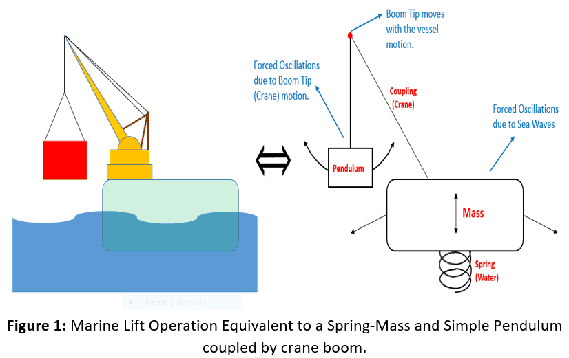
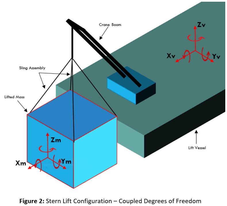
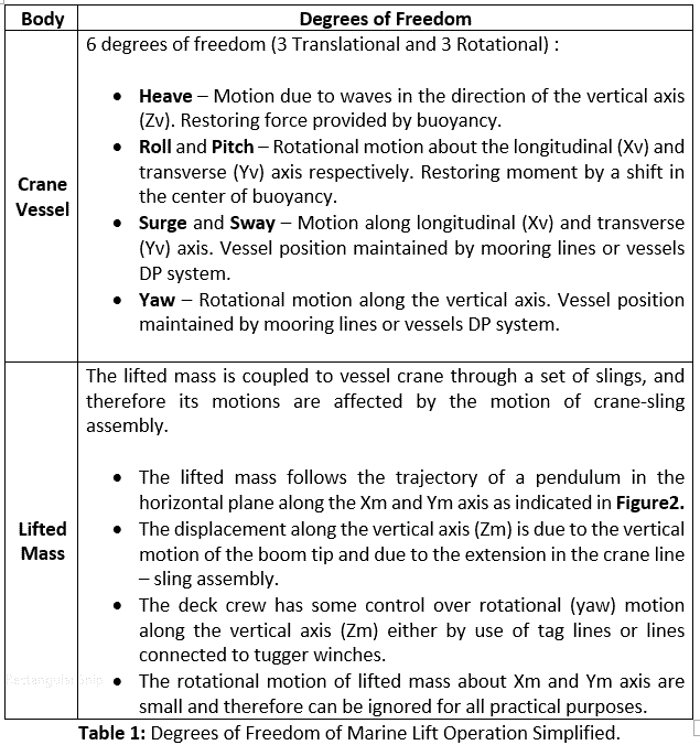
Figure 2 shows the isometric view of the stern lift configuration with coupled degrees of freedom. In Table-1, I have attempted to further simplify the problem by evaluating the degrees of freedom of each body individually.
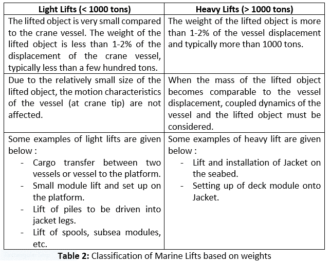
Lift Classification
Typically, marine lifting operations are divided into two categories depending on the weight as presented in Table-2:
Operational Constraints
Now that we have understood the physical nature of marine lift operation, our next step is to look at the operational constraints that need to be considered during the engineering and planning phase. As an engineer, it is imperative to understand the risks associated with the offshore operation and be well versed with the industry guidelines/ lessons learned for safe execution of the job. Although every lift operation is different and may have unique operational constraints that need to be addressed, I have listed the main things that must be considered.
Resonance (Pendulum Instability)
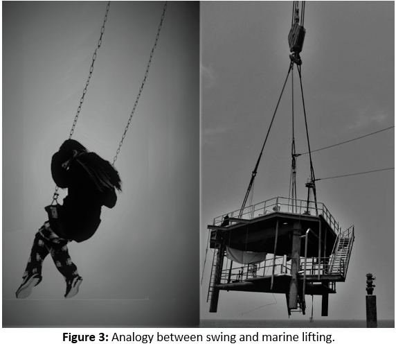
Remember, when you were a kid, and to start swinging, you would move back and forth on the swing seat in just the right frequency such that swing would oscillate with larger amplitudes. In simplest terms when a system is oscillated at or close to its natural frequency, it will exhibit the phenomenon of resonance, and the oscillations will become wild and in some cases undesirable. Similarly, in a marine lifting operation, we have a hanging mass (just like the swing) which is forced to oscillate (in the horizontal plane) due to the crane tip motion which in turn is governed by the motion of the lifting vessel in sea waves. In this scenario, large oscillations due to resonance may occur if the frequency of the crane tip motion gets close to the natural frequency of oscillation of hanging mass.
The large motion of lifted load is not acceptable mainly due to the risk of collision with the crane boom, crane vessel or nearby structures. Therefore, it is crucial to analyze a marine lift operation for a range of wave periods representing the environmental conditions at the lift location. As per London Offshore Consultant guidelines for marine lifting operations, a minimum clearance of 3m between lifted object and crane boom should be maintained at all times. Another thing that needs to be kept in mind when dealing with resonance is that the natural frequency of simple pendulum changes with the suspended length of mass as per below equation:
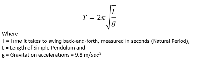
In the case of marine lifting, the distance between the boom tip and center of gravity of lifted load varies throughout the operation. The mass may be lifted off the material barge to required elevation and then lowered onto the jacket in case of deck lift or lowered to the seabed in case of subsea lift. Therefore it is crucial to analyze the system at different operational stages to capture maximum motions due to resonance.
Dynamic Amplification Factor
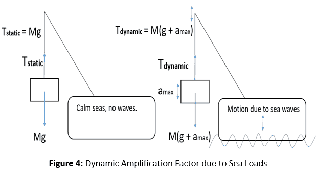
As we know that a floating body at sea is exposed to dynamic loads due to waves and therefore any part of the body is in constant motion. The lifted mass is connected to the crane boom by a set of slings and moves due to the motion of the crane boom. Therefore, the maximum hook load is the sum of gravitation force and the force due to the maximum acceleration of the lifted mass as given by the equation below:
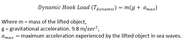
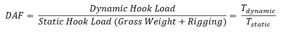
Dynamic Amplification Factor (DAF) by definition is the ratio of Dynamic Hook Load and Static Hook Load as given below:
It is important to note that the maximum dynamic hook loads should be considered when designing rigging for marine lift operation.
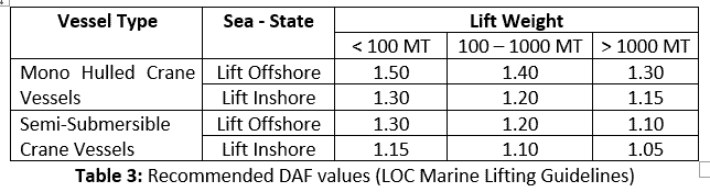
Table 3 summarizes the DAF values to be used in the absence of dynamic response analysis as per LOC marine lifting guidelines. Note that DAF values are lower in the case of inshore (sheltered waters) due to reduced wave loads. In addition, the motion response of a semi-submersible is lower compared to a monohull, and consequently, it has reduced DAFs. It is also interesting to note that DAF values are typically lower for heavier decks for the same sea-states. This can be attributed to the fact that heavier decks have greater mass (inertia) and therefore lesser acceleration for the same wave loads.
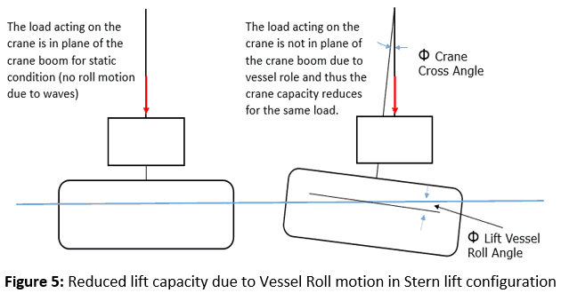
Crane Cross Angles
The crane cross angle is defined as the angle between the hook load line and the vertical plane of the boom. For a lift fixed over the stern of a derrick barge, the cross angle is primarily caused by the vessel roll motion whereas, for lifts over the side of a derrick barge, the cross-angle results from the barge pitch. Typically for an over the stern, fixed (highest capacity) lift, the crane cross angle would be limited to 1.0 degree (single amplitude maximum value) and for an over the side, or over the stern, revolving capacity lift, this would be limited to 3.0 degrees (single amplitude maximum value). However, the limiting cross angles do vary between cranes, based on the crane sheave design and the limiting lateral loading capacity on the crane boom and therefore, the crane charts should be used to check the ultimate lift capacity. Figure 5 shows the effect of vessel roll on the lift capacity of the crane.
Marine Lifting Case Study
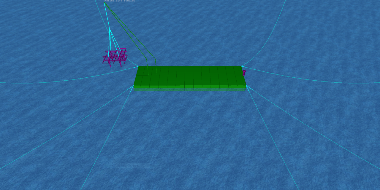
Now that we have understood the operational constraints involved in a lift operation let’s analyze a simple scenario of a crane barge lifting a deck module. I will use Bentley’s MOSES software as the prime tool due to its flexibility in dealing with a multi-body problem involving mechanical and hydrodynamic coupling. I will get into the detail of inputs and outputs for a clear understanding. Like in my previous article I’ll re-emphasize that MOSES is a great tool; however, the engineer using it should have a clear understanding of the theory behind the problem at hand and not just blindly feed inputs to get results.
Lift Configuration and Setup
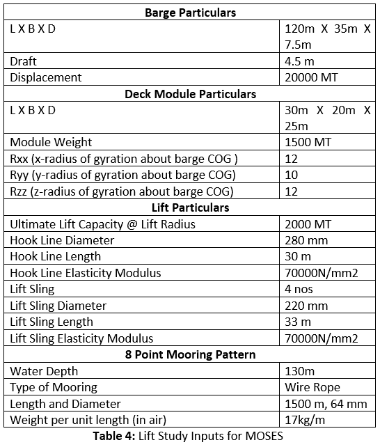
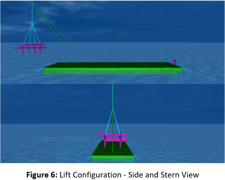
A typical rectangular shaped crane barge has been considered for the case study. Properties of the lift barge and the lifted module are summarised in Table 4. As mentioned before, a typical offshore heavy lift operation can be treated as a single lift operation involving a two-body system comprising a crane vessel and lifted module. The side and stern view of the lift operation are shown in Figure 6. The initial clearance between the derrick barge and topside is 6.0 m.
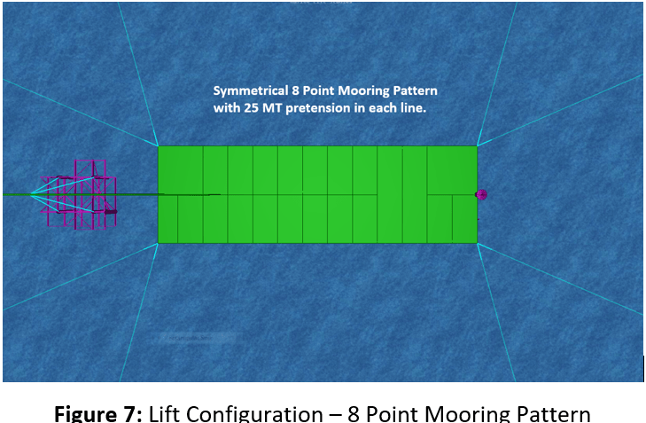
The barge is moored using an eight (8) point mooring system as shown in Figure 7. It is to be noted that crane tip motions vary with lift radius and therefore the crane radius directly impacts the dynamics of lift operation. To maintain sufficient clearance between the derrick barge and the topside, and achieve sufficient lift capacity, a lift radius of 40 m is used in the analysis.
Numerical Modeling In Moses
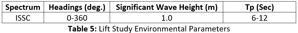
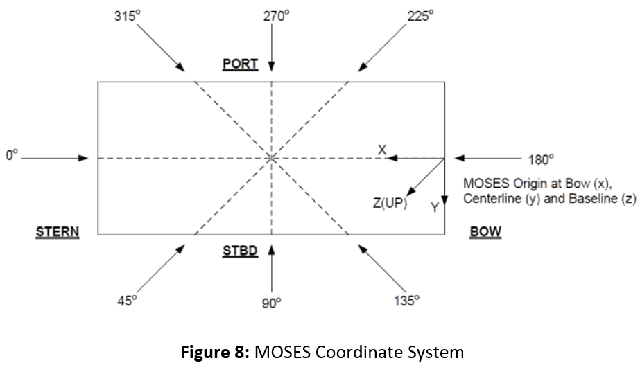
A hydrodynamic model of the rectangular barge is generated in MOSES software. The model of the Deck Module is input as a truss using beam elements and created with all lift points. The deck module is connected to the crane boom of the derrick barge using hoisting wire, ignoring the stiffness of the crane to simplify the modeling. MOSES has simplified the modeling of the crane lift sling system using a ‘tip-hook’ function which defines the sling assembly in the model. All bodies are connected to form one integrated dynamic system to account for mechanical coupling of the system. Lift barge is kept in position using the mooring pattern as shown in Figure 7. MOSES considers steady-state loading from current, wind and wave drift and oscillatory loading from waves and low-frequency components of wave/wind drift. The required hydrodynamic database is generated using the ‘3-D diffraction theory’. The analysis is performed in the time domain using ISSC (International Ship Structures Congress) spectra for environmental parameters as shown in Table 5. MOSES coordinate system is provided in Figure 8.
Dynamic Amplification Factor (DAF) on the crane hook is evaluated from dynamic load acting on the hook which is calculated by MOSES for different sea state and headings. The operational limitations due to restrictions imposed by crane cross angle, the minimum required clearances, and dynamic amplification factors have been captured from the analysis for each wave heading and period.
Results and Discussion
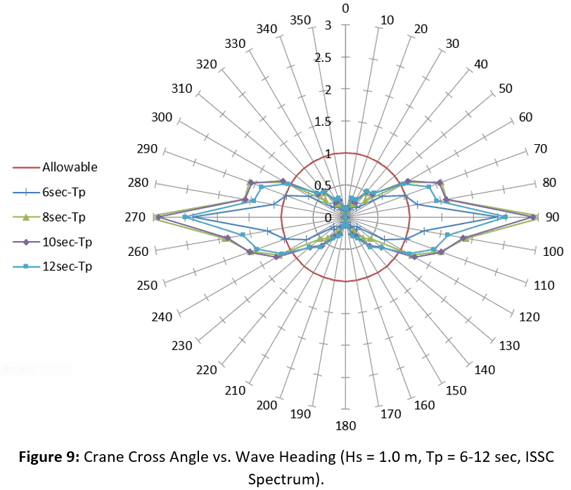
Predicted maximum crane cross angles have been extracted from the time domain simulations and plotted for the environmental parameters (refer Table 5) as shown in Figure 9. The maximum allowable cross angle for stern lift configuration is 1 deg. It is no surprise that the barge roll motion and therefore the crane cross angle is maximum for beam seas. Note that in this case the cross angles exceed the maximum allowable (1 deg.) for beam sea configuration and therefore the lift operation is weather dependent (in beam seas) and may only be feasible in lower sea-states corresponding to lower significant wave heights.
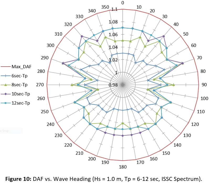
The DAF for 1.0 m Hs has been plotted for various wave periods and headings as shown in Figure 10. DAF for all the wave periods is less than 10 percent of the static lift weight.
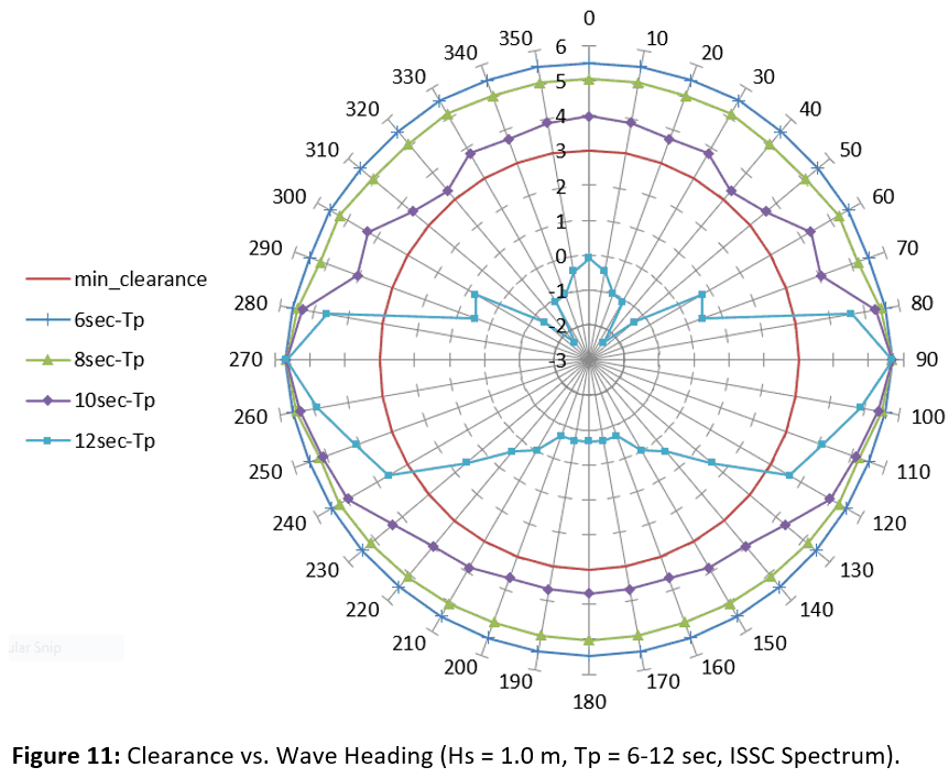
The dynamic clearance between the deck and the barge for 1.0 m Hs has been plotted for various wave periods and headings as shown in Figure 11. It can be seen that a minimum clearance requirement of 3 m (between the barge and deck) is met for all peak periods except 12 seconds. As expected the clearance between barge and deck is less for head and stern seas compared to beam seas.
In the end, I would like to say that every marine lift operation is unique and may have special constraints. Engineers should methodically understand every aspect of the lift operation and perform engineering analysis keeping in mind the unique constraints of the operation. Due diligence saves time, money and lives.
Feel free to share this article and post comments if any. I would also like to have suggestions for topic of my next article.
Until next time, have a great day.

Rahul Kanotra, C.Eng.
Consultant Naval Architect, Installation Engineering Expert
Mr. Rahul Kanotra is a Consultant Naval Architect and Hydrodynamic Expert with extensive experience in large offshore projects, front-end design, and other aspects of installation engineering. He holds a Master’s and Bachelor’s degree in Naval Architecture and Ocean Engineering from Indian Institute of Technology, Madras. He has worked on multiple Research & Development projects and published and presented technical research papers in esteemed international conferences. Mr. Kanotra has extensive experience in numerical and experimental analysis of floating and fixed offshore platforms. He has provided his engineering expertise for multiple Offshore installations across the globe. Mr. Kanotra can be contacted at rahulkanotra2004@gmail.com and through link to his LinkedIn profile https://www.linkedin.com/in/rahul-kanotra-ceng-mtech-mrina-95876941/.
Disclaimer:
The views, information, or opinions expressed during [the] series are solely those of the author and do not necessarily represent those of Thenavalarch Pte Ltd and its employees
-
Mooring Forces Calculator (Stern on Quay, 4-Point Mooring)
$99.00 Add To Cart -
Mooring Forces Calculator (Port or Stbd on Quay)
$99.00 Add To Cart -
OCIMF Environment Forces Calculator – Tankers (Updated toMEG-4)
$99.00 Add To Cart -

OCIMF Environment Forces Calculator – Gas Carrier (updated to MEG4)
$99.00 Add To Cart -
Capstan Design (Required power for Berthing)
$49.00 Add To Cart -
Sale!
Fender Design (Berthing Energy Calculator – Side Berthing)
Original price was: $69.00.$49.00Current price is: $49.00. Add To Cart -

SPMT Loadout Ramp Design Spreadsheet
$69.00 Add To Cart -
Bollard Pull Calculations for Barge
$49.00 Add To Cart -
Bollard Pull Calculations for Ships
$79.00 Add To Cart -
Cargo Forces & Accelerations – Open Ocean
$49.00 Add To Cart -

Pipe Stacking Height Calculator (Bare Steel Pipes)
$39.00 Add To Cart -

Pad-Eye Design Spreadsheet
$49.00 Add To Cart -
Stopper Design Spreadsheet
$49.00 Add To Cart -
Dog Plate Design Spreadsheet
$49.00 Add To Cart -

Bollard Strength Check Spreadsheet
$39.00 Add To Cart -

Smit Bracket Design Spreadsheet
$49.00 Add To Cart -

Towline (Static) Catenary Calculator
$39.00 Add To Cart -
Ship Squat Calculator
$49.00 Add To Cart -

Towing Bridle Design Spreadsheet
$39.00 Add To Cart -

Stanchion Design Spreadsheet
$49.00 Add To Cart -

Pipe Stowage Plan Spreadsheet
$29.00 Add To Cart -

Towing Bridle Force Calculator
$29.00 Add To Cart -

2-Hook Lift Factors & Lift Point Loads
$49.00 Add To Cart -

Lashing Design (4 Point Lashing, IMO CSS)
$49.00 Add To Cart -
Mooring Line Catenary App
$99.00 Add To Cart -

Stacking Height Calculator (Concrete Coated Pipes)
$49.00 Add To Cart -
Motion Response Calculator
$99.00 Add To Cart -
Single Point Lift Design Spreadsheet
$49.00 Add To Cart -
DNV Ship Motion Calculator
$99.00 Add To Cart -
Two point (single hook) lift design (as per DNV)
$49.00 Add To Cart

thank you