Resistance estimation for a vessel is a fundamental exercise in design of the vessel. Resistance is a property that depends on the vessel’s shape and form. A conventional ship-shaped vessel with a bulb will have completely different resistance characteristics compared to a high-speed planing vessel.
Resistance estimates are done using various methods – by hydrodynamic modeling/CFD analyses or by model testing for accurate estimates, or by using empirical relations in the preliminary design phase for a fair estimate of the resistance.
Empirical relations too vary depending on the vessel type. While Holtrop-Mennen method is the most popular one that is used for conventional ship forms (usually merchant vessels), it does not apply to high-speed hulls and planing boats.
Planing vessel resistance calculator – TheNavalArch
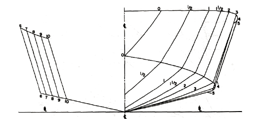
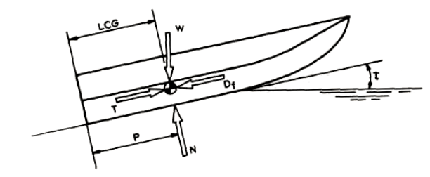
A planing vessel is distinguished form a conventional displacement vessel by the mechanism of weight support. While for a displacement vessel, the buoyancy of the vessel supports its weight, a planing vessel supports its weight by the hydrodynamic lift forces generated when the vessel moves at high speed over water. When the planing vessel is at rest or at low speeds, its weight is supported by its buoyancy, but as it moves with higher speeds, hydrodynamic lift forces are generated by the specially designed hull shape of the planing craft and these lift forces fully support the hull. In some crafts the lift and buoyancy both support the weight. A typical body plan of a planing craft is shown below:
In this article, we will look into a theoretical approach to estimating a planing craft’s performance. A number of resistance tests have been performed by Savitsky (1964) to determine formula for lift and drag of planing vessels, and empirical relations have been provided for the drag.
In this method, at equilibrium, part of the lift is generated by Buoyancy while the rest is generated as hydrodynamic lift. The important parameters of the vessel like its dimensions, speed, displacement etc are taken as inputs, and parameters like trim angle, wetted length of the keel etc. are determined. These parameters are then used to determine the resistance of the vessel.
The method and steps can be broken down into the following:
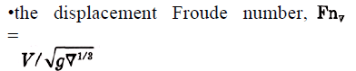
- Step 1 – Calculate the Displacement Froude number: The first parameter to be calculated is the displacement Froude number. It is defined thus
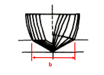
- Step 2 – Calculate the Froude number based on ‘b’: Here, ‘b’ is the maximum beam of the vessel over chine or spray strips. This is the beam of the planing area of the vessel
CV = V/√(gb)
Planing vessel resistance calculator – TheNavalArch
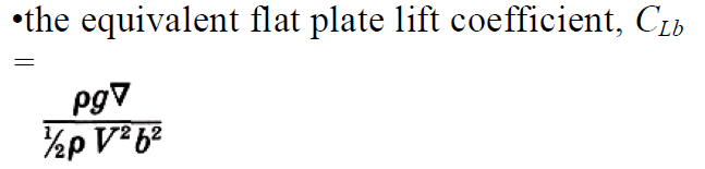
- Step 3 – Calculate the equivalent flat plate lift coefficient: This is calculated by using the formula:
- Step 4 – Calculate the lift coefficient for a finite deadrise: Depending on the deadrise angle β, the lift coefficient for a finite deadrise is calculated from the flat plate lift coefficient by using the following formula:
![]()
- Step 5 – Calculate the p/b ratio, where p = longitudinal center of gravity (LCG) of the vessel (see below)
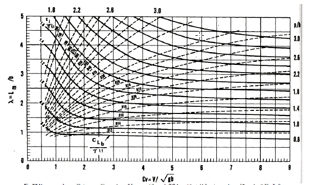
- Step 6 – Calculate the mean wetted length-beam ratio: This is the ratio λ = Lm/b, which is obtained from the Koelbel’s curves.
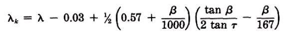
- Step 7 – Calculate the trim of the vessel in equilibrium: This is calculated by using the Savitsky formula:
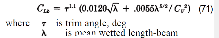
Here λ is the ratio of the mean wetted length to the beam of the planing area, i.e., Lm/b, obtained in Step 6
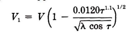
- Step 7 – Calculate the keel-wetted length ratio: This is calculated by using the formula:
- Step 8 – Check if the vessel is fully planing: If λk <= LWL/b, then it is fully planing, i.e., the bow is clear of water, else it is not. If it is fully, planing, then the method is valid, else this method is not applicable for vessels not fully planing
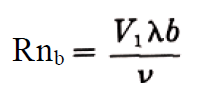
- Step 9 – Use the formula to calculate resistance:

W is displacement. Here, CFO is calculated from ITTC Line, using the following formula
CFO = 0.075/(log10Rn -2)2
Do check our our product Planing Vessel Resistance Calculator
References
- https://en.wikipedia.org/wiki/Planing_(boat)
- Principles of Naval Architecture Second Revision, Volume II Resistance, Propulsion and Vibration
Disclaimer: This post is not meant to be authoritative writing on the topic presented. thenavalarch bears no responsibility for the accuracy of this article, or for any incidents/losses arising due to the use of the information in this article in any operation. It is recommended to seek professional advice before executing any activity which draws on information mentioned in this post. All the figures, drawings, and pictures are property of thenavalarch except where indicated, and may not be copied or distributed without permission.
Webcast: Rapid Rigging
Learn a rapid and practical method for generating accurate rigging arrangements and estimating rigging loads in one hour or less using simple engineering principles and streamlined workflows. TECHNICAL WEBCAST OVERVIEWLifting operations can be executed far more...

TheNavalArch’s Interview Series: Peter Farthing (MD, Sensor Technologies)
Peter FarthingManaging Director of Sensor Technologies Ltd and CEO of Advantec Group Limited Interview Introduction TheNavalArch's Interview Series is an endeavor to get insights from the best engineering and business brains in the industry and present them to its...
TheNavalArch Interview Series: Capt Robin Perera
TheNavalArch's Interview Series is an endeavor to get insights from the best engineering and business brains in the industry and present them to its users for the larger benefit of the maritime community. Leaders share their experiences and ideas that readers can gain...
Offshore Installation Vessels Stability Considerations
OFFSHORE INSTALLATION VESSELS STABILITY CONSIDERATIONS By Alan Crowle, BSc, MSc, MScbyRes, CEng, CMarEng, FRINA, FMAREST, FSCMS University of Exeter, College of Engineering, Renewable Energy Group INTRODUCTION The temporary phases of an offshore structure transport...
TheNavalArch Interview Series: Mr Victor Valera
TheNavalArch's Interview Series is an endeavor to get insights from the best engineering and business brains in the industry and present them to its users for the larger benefit of the maritime community. Leaders share their experiences and ideas that readers can gain...
TheNavalArch Interview Series: Mr Steven Lu
Mr. Steven LuManaging DirectorEpoch Offshore Engineering (Shanghai) Co., Ltd. TheNavalArch's Interview Series is an endeavor to get insights from the best engineering and business brains in the industry, and present them to its users for the larger benefit of the...
TRANSPORT VESSELS FOR FLOATING WIND
By Alan Crowle, BSc, MSc, CEng, CMarEng, FRINA, FMAREST, FSCMS Masters by Researcher, University of Exeter, College of Engineering, Mathematics and Physical Sciences, Renewable Energy Group SUMMARY Floating wind turbine construction is a large logistical exercise. The...
TheNavalArch Interview Series: Mr. Balakrishna Menon
Mr. Balakrishna MenonEngineering Director Mooreast (Asia) Pte Ltd TheNavalArch's Interview Series is an endeavor to get insights from the best engineering and business brains in the industry, and present them to its users for the larger...
Floating Rice Fields, the quest for solutions to combat drought floods and rising sea levels
by Lim Soon Heng, BE, PE, FSSS, FIMarEST Founder President, Society of FLOATING SOLUTIONS (Singapore) Abstract Amazing as it seems, there is a case for growing rice on floating platforms in the sea. The capital expenditure to develop this is offset by the opportunity...
CAPSIZE OF LIFTBOAT IN TRANSIT
This paper was originally presented in the 27th Offshore Symposium, February 22nd, 2022, Houston, Texas Texas Section of the Society of Naval Architects and Marine Engineers It has been reproduced here for the readers of TheNavalarch INTRODUCTION In 1989 a Class 105...
Please check out TheNavalArch’s product for planing vessel resistance estimation:

Hi Prem,
I will read this with much of interest.
Brgds
Costas