Stoppers and their critical role in seafastening of cargo

Introduction
A cargo transported on the deck of a ship is subject to many forces. These forces comprise of the inertial forces due to the ship motions – the three translations and three rotations – and the environmental force of wind.
Due to the combined effect of these forces, the cargo, if left unfastened on the deck of the vessel may not remain static at one location but may move around. To avoid this, it is critical that the cargo is restrained from movement. The design of all accessories to restrain the cargo is called Seafastening design.
A typical and simplest seafastening may comprise of lashing ropes (or wires) fastened to pad-eyes welded on deck of the vessel. However, for some heavy cargoes this may not be enough, and additional arrangements may be required for preventing both translational and rotational motion of the cargo on deck.
A Stopper is a simple structure which is welded to the deck of the vessel to prevent the cargo from sliding (i.e., the translational motion).
The very simplest stopper which can be imagined is simply a metal plate which is welded to the deck, and against which the cargo rests. The below figure should be able to provide a starting point.
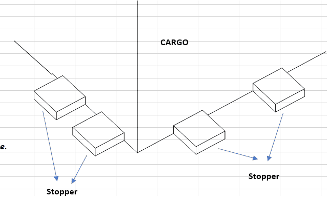
The simplest stopper comprising of a steel bar
Types of Stoppers
Stoppers can be of many types. The choice of the right stopper depends on the geometry of the cargo, on the weight distribution of the cargo and on forces experienced by the cargo during the voyage. Stoppers can range from simple plate bars to complex H-beams (called Stanchions on ships).
Some of them are shown below:
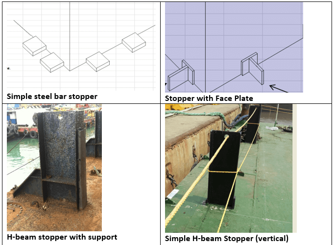
Types of Stoppers
For example, the H-beam stoppers (also called stanchions) are mostly used for restraining pipes being transported. A box shaped cargo with most weight near its base will use a flat plate stopper (with or without face plate).
![]()
H-beam stoppers (stanchions) used for restraining pipes
The height of the stopper will depend upon the height where the cargo needs to be supported. For example, in the above pic showing stoppers for pipe transport, the stanchions need to be of a height more than the diameter of the pipe to secure the whole pipe bay adequately. Similarly, box shaped cargo like containers may find the simple steel bar stopper (or one with face plate) enough for restraining.
Structural Design of a Stopper
Whatever the shape and type of stopper selected, it should be structurally sound to perform its job – preventing the sliding of cargo, i.e., it should be able to overcome the forces which make the cargo slide. What are these forces?
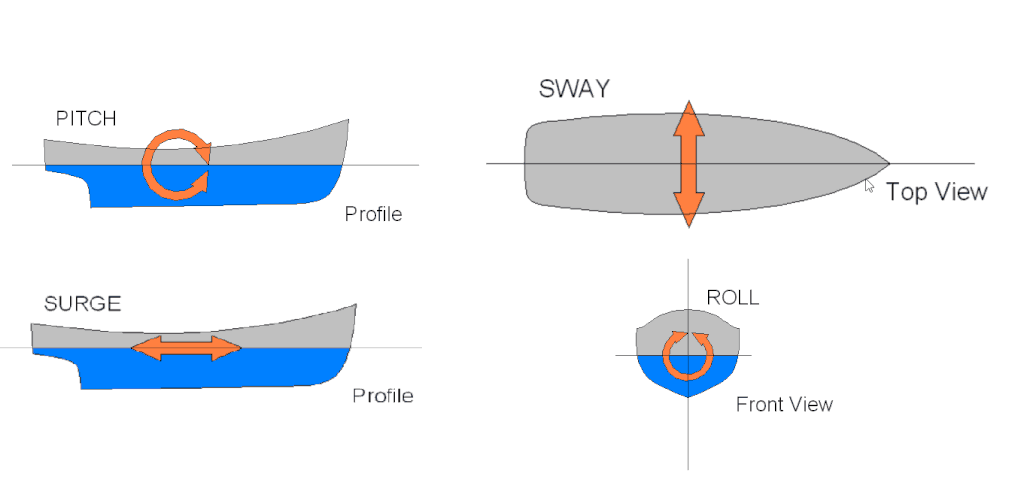
he two forces which may lead to cargo sliding are:
- Transverse force, or the force which makes the cargo slide athwartship, i.e., Port and Starboard. This force arises due to sway and roll motion of the ship
- Longitudinal force, or the force which makes the cargo slide forward/aft. This force arises due to the surge and pitch motions of the ship.
The figure below demonstrates the two sliding forces.
To understand the structural design of a Stopper, let’s take an example of a box shaped cargo being restrained by a flat steel stopper with a face plate.
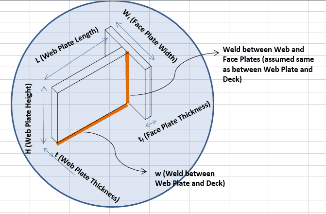
Stopper with a Face Plate
This kind of stopper has two components – a web plate and a face plate which are welded to each other. The face plate is what the cargo rests against, while the web plate is welded to the deck of ship. The details of the weld and configuration of the plate can be seen in the figures above.
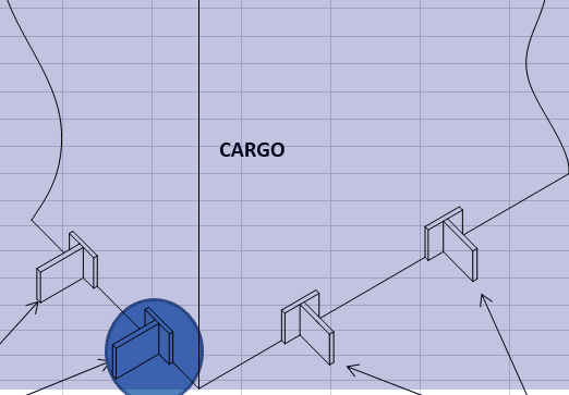
Since the vessel experiences forces both in longitudinal and transverse directions, stoppers need to be installed on both longitudinal and transverse faces of the cargo. Taking a simple box shaped cargo as an example, a typical plan showing the stoppers is shown below. We can see that three stoppers on each side (Port/Stbd) are restraining the total Transverse force (FT), while two stoppers on each side (Fwd/Aft) are restraining the Longitudinal force (FL). The forces can be obtained from a motions analysis of the vessel, or using some empirical formulae (check out our products for calculating accelerations)
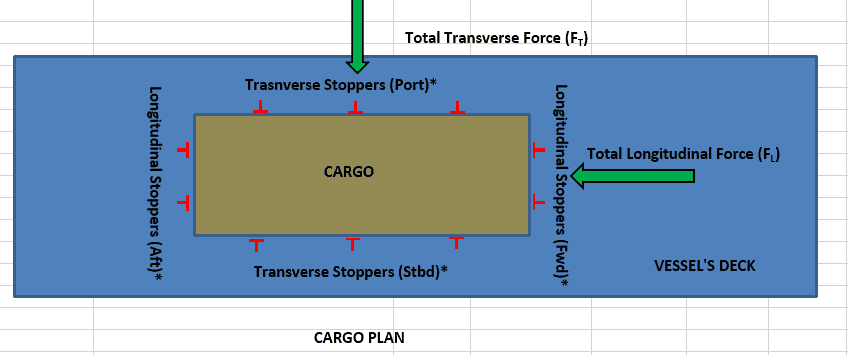
From the figure above, we can see that each transverse stopper takes one third of the total transverse force, while each longitudinal stopper takes one-half of the total longitudinal force.
Total force on each transverse stopper = FT / 3
Total force on each longitudinal stopper = FL /2
Zooming down to a single stopper (whether transverse or longitudinal), it will experience a force which is FT / 3 for transverse stoppers and FL /2 for longitudinal stoppers. Let’s call the force as Fd (Design Force). The design force acts on the face plate of the stopper. The location on the face plate where the force acts can vary depending on how the face plate is in contact with the cargo, but for simplification, we consider that the force is a point force acting at mid-height of the face plate. The figure below depicts this.
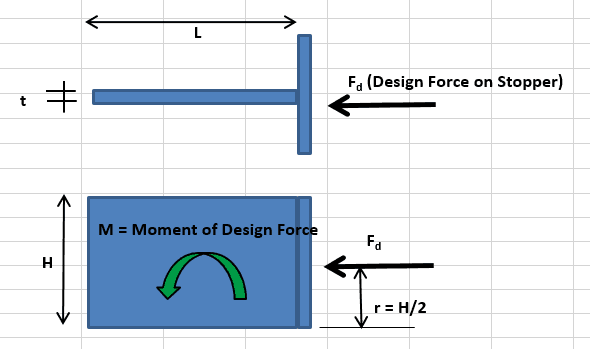
The force on the Face Plate is effectively transmitted to the web plate which is welded to the deck. This leads to a shear force on the web plate. Further, the force, acting at a height of H/2 (where H is height of face plate) leads to a turning moment which is transmitted to the base of the web plate, where the web plate is welded to the deck.
Thus, we need to analyze the web plate for:
- Shear Stress due to force Fd
- Bending Stress due to moment Fd x H/2
Weld Strength Check
Since the weld is what affixes the web plate to the deck, the stresses in the weld are equally important to be evaluated.
Usually the weld type for welding the web to the deck is a fillet weld (two-sided). The weld profile for the stopper with face plate is shown below:
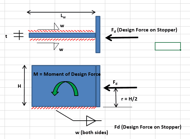
The force Fd and the resulting moment M are transmitted to the weld which is analyzed for:
- Shear stress on the weld
- Bending stress on the weld
- Total (combined) stress on the weld
With the above two types of checks (web plate strength check and weld strength check) performed, the stopper’s structural design is considered enough.
Similar principles can be applied to the design of other types of stoppers (H-beam stoppers or Stanchions).
To wrap up, stoppers are small structural items but play a vital role in retraining cargo during transport. Thus, their design should be done with due diligence and care to ensure a successful marine operation.
Please do check out our related products below:
- Stopper Design Spreadsheet
- Stanchion design spreadsheet
3. Cargo Forces and Accelerations Calculator
4. DNV Ship Motions Calculator
About the Author:

Prem Shankar, Naval Architect
The author is the founder of www.thenavalarch.com, a website which aims to bring the marine and oil & gas industries to the internet through rich in quality but low in cost online content like useful calculators, video tutorials and articles. A graduate in Naval Architecture from Indian Institute of Technology (IIT), Kharagpur, he has more than 15 years of work experience in Singapore and India working with industry leaders like Mcdermott and Bumi Armada on the design, engineering, construction and installation of a variety of marine and offshore structures, ranging from ships to offshore platforms and FPSO’s. He also had the honor to serve as the Vice President of Society of Naval Architects and Marine Engineers Singapore from 2015-2017.
TheNavalArch is his endeavor to create a platform which brings out the knowledge currently lying with industry experts and places it on the web for everyone to benefit from. He’s constantly looking for collaborators who are interested in creating rich content and contributing to the growth of this platform and to the industry at large. Interested experts can contact him at info@thenavalarch.com
Disclaimer: This post is not meant to be an authoritative writing on the topic presented. thenavalarch bears no responsibility for the accuracy of this article, or for any incidents/losses arising due to the use of the information in this article in any operation. It is recommended to seek professional advice before executing any activity which draws on information mentioned in this post. All the figures, drawings and pictures are property of thenavalarch except where indicated, and may not be copied or distributed without permission.
