Loadouts are a complicated exercise and require intricate engineering calculations to ensure success of the operation. Right from selecting the suitable vessel with adequate ballasting capability, to performing ballasting and stability calculations, selection of the loadout method (skidded/SMPT/lifted) down to the selection of the loadout ramp, each activity carries an equal significance.
In this article, we’ll discuss the significance, and design aspects of loadout ramps. Loadout ramps are structures which are used to cover the gap between the quayside and the vessel (for skidded/SPMT loadouts). The cargo is transferred from Quay to Vessel as it is skidded over the Ramp or when a SMPT trailer carrying the cargo moves over the ramp.
We can sense that during the loadout operation, the ramp must stay horizontal to avoid any unwanted scenarios of the load tilting or the vessel suffering from strength issues. This is ensured by a carefully monitored ballasting operation which keeps the vessel on even keel and level with the quay even during tidal variations.
The picture below depicts a loadout operation using a SPMT trailer. We can see the ramps at the left-hand bottom corner of the picture.
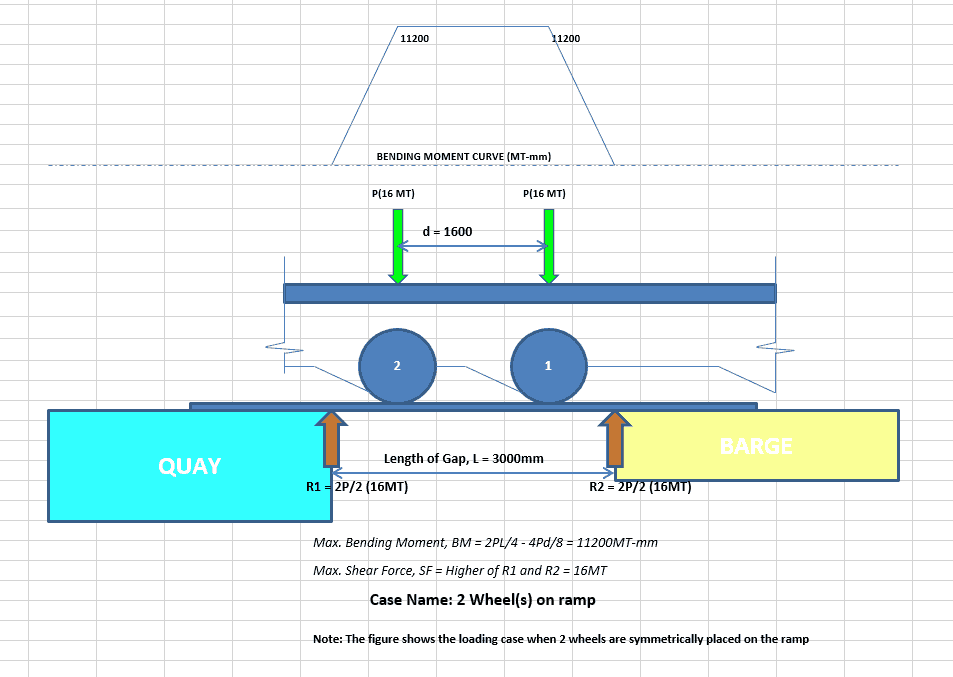
 Case 2 is also depicted below. We can see that now there are two wheels equidistant from each end of the gap. Each wheel carries a load of 16 MT, and the resulting bending moment and shear force curves are also shown.
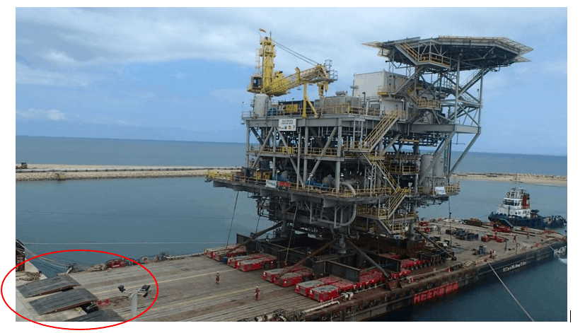
A loadout using a SPMT trailer (source: www.nesoffshore.com)
These ramps appear to be rectangular, but wedge shaped. We can also notice that there are four files of SPMT trailers and there is one ramp placed for each file (only two ramps are fully visible, while the third is partially visible). Looking at these ramps and imagining the SPMT going over the ramp, we can gauge the kind and distribution of forces the Ramp will be undertaking during the operation.- As the wheels of the SPMT leave the quay side and get on to the ramp, load starts getting transferred to the ramp.
- When the first wheel moves in, the ramp will experience the quantum of load which the first wheel of the SPMT carries.
- Generally, the load of the cargo is spread onto the wheels of the SPMT and it can be considered that each wheel/axle carries a uniform load which equals the weight of cargo divided by the number of axles.
- The load from each wheel/axle can be considered as a point load on the ramp as a simplification
- The load distribution on the ramp will depend upon
- Length of gap between SPMT and vessel
- The distance between the axles/wheels of SPMT.
- Depending on the above factors, there can be different cases of loading on the ramp
- One wheel at the center of the ramp
- Two wheels equidistant from the sides of the gap
- Three, four or more wheels, depending on relative difference between the length of gap and distance between two wheels/axles.
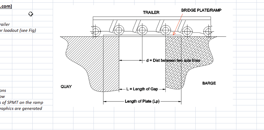
Figure depicting a SMPT loadout trailer on a flat plate ramp
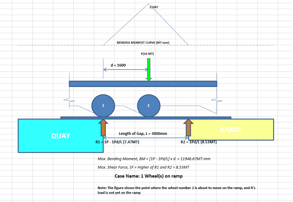
Example calculations To demonstrate the different load scenarios, lets take an example of a scenario of loadout with the following parameters:- Length of gap = 3000 mm
- Distance between two axle lines = 1600 mm
- Load per axle = 16 MT
- Plate dimensions = 6000 mm x 2000 mm x 50 mm THK
- Case 1 – one wheel on ramp
- Case 2 – two wheels on ramp
Case 2 is also depicted below. We can see that now there are two wheels equidistant from each end of the gap. Each wheel carries a load of 16 MT, and the resulting bending moment and shear force curves are also shown.
Disclaimer:
The views, information, or opinions expressed during [the] series are solely those of the author and do not necessarily represent those of Thenavalarch Pte Ltd and its employees

Prem Shankar
Founder, TheNavalArch
The author is the founder of www.thenavalarch.com, a website providing useful low-cost software and other online resources for Naval Architects. A graduate in Naval Architecture from Indian Institute of Technology (IIT), Kharagpur, he has worked on the design, engineering, construction and installation of a variety of marine and offshore structures, ranging from ships to offshore platforms and FPSO’s. TheNavalArch is part of his endeavour to bring rich and low-cost online content for the oil & gas and marine communities. The author can be contacted at info@thenavalarch.com

Send complete information and quotation.
Hi, I am designing RORO quay.
So I am very interested in this article.
Thank you.