Introduction
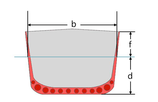
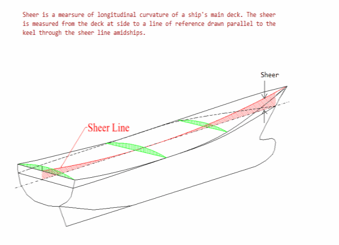
Freeboard is a common term used in vessel operations. Freeboard is the smallest vertical distance between the waterline and the freeboard deck (generally the upper deck) along the length of the vessel. The term ‘smallest’ is of significance, as the height of the deck above the vessel’s baseline may vary along the length of the vessel due to sheer – this leads to difference in the vertical distance between the deck and the waterline at different points along the vessel’s length.
Freeboard of a ship ‘f’ in picture above (Source: Wikipedia)
A higher freeboard indicates a higher reserve buoyancy of the vessel, which is the volume of the spaces above the waterline. This lends better stability to the vessel, but leads to higher weight of the vessel. Vessels with more openings on the deck (i.e., susceptible to more rapid flooding) are expected to have higher freeboard, while vessels which have the deck with minimum or no openings (like tankers) are expected to have lower freeboards.
In this article, we will understand the what, why, and how of freeboard calculation for a vessel.
Freeboard Calculation – considerations
The calculation of freeboard is carried out as per the International Convention on Load Lines, 1966, as Amended by the Protocol of 1988 – Annex I – Regulations for Determining Load Lines.
Thinking about the basic purpose of assigning freeboard to a vessel, we can find out what factors or calculations will go into play when determining it.
The basic purpose while assigning the right freeboard is to ensure that the vessel has sufficient reserve buoyancy.
Thinking in basic terms, what factors or items can contribute to the reserve buoyancy of a vessel?
- Size of the vessel – a bigger vessel needs higher reserve buoyancy, and thus its freeboard shall be higher than a smaller vessel
- Structural integrity of the vessel – A vessel with many large hatch openings on the deck is likely to have more compromises on the ‘intactness’ of its structure. Comparatively, a vessel with high integrity of the main deck – vessels carrying liquid cargoes/tankers – will be more intact and will have a lower need for reserve buoyancy.
- Other factors that affect reserve buoyancy – any other factor that affects reserve buoyancy shall have to be taken into account
- If there is superstructure that can contribute to reserve buoyancy, then the freeboard can be reduced
- If there’s additional sheer in the vessel, then the reserve buoyancy goes up and freeboard can be reduced
Tabular Freeboard (Regulation 28 of ICLL)
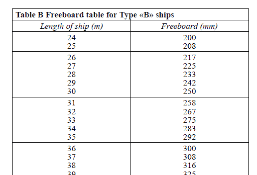
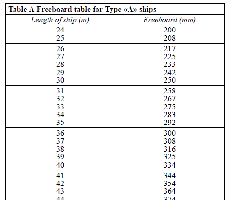
The approach to freeboard calculation as laid out in ICLL 66 is to first calculate the standard freeboard that is attributable to the vessel. The ICLL 66 provides standard tables for the minimum freeboard needed, depending on the length and type of ship. There are two types of ships recognized:
- Type A – tankers and other liquid carriers with high integrity of the main deck
- Type B – those which are not Type A
The typical table is shown below:
Consideration for some Type-B ships:
- B-60 and B-100 Freeboards (Regulation 27 of ICLL) Certain Type B ships in which the structure can be demonstrated to have additional provisions to obtain integrity similar to Type A ships, then they can claim a further deduction in freeboard. The deduction can be between 60% and in some cases also 100% of the difference in freeboard of the Type B and Type A vessel. Such Type B vessels are called B-60 or B-100 vessels (the numbers indicate the percentage deduction)
- The additional conditions required for a Type-B ship to get the deduction are specified in Reg 27 of ICLL
- Correction for wooden hatches (Regulation 27 of ICLL) – Type B ships which have wooden/tarpaulin hatches and hatches not made of steel will need a higher freeboard
- Correction for type B ships with length less than 100 m (Regulation 29 of ICLL) – Type B ships which are less than 100 m in length and with superstructure whose effective length is less than 35% of the vessel’s length will have a higher freeboard. This is due to the fact that a smaller vessel with smaller superstructure will pitch more, and the reserve buoyancy provided by the superstructure will not be sufficient.
The Standard Ship, and corrections to freeboard
We can see that the freeboard varies with the length of the vessel.
It is noteworthy that the above tabular freeboards are provided for a standard ship. A ‘standard ship’ means a ship:
- a block coefficient Cb of 0.68;
- a length to depth ratio of 15 i.e. L/D = 15;
- no superstructure;
- a parabolic sheer of the freeboard deck attaining a particular height at the forward and after
- perpendiculars as prescribed by formulae (depending on the length of the ship);
- a minimum bow height above the load waterline as prescribed by formulae (depending on
block coefficient Cb and length of the ship).
This also means that any ship which deviates from the ‘Standard ship’ in any of the factors specified above, will need some adjustment to the tabular freeboard. These adjustments are called ‘corrections’. These corrections are listed below:
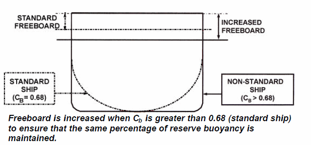
- Correction for block coefficient (Regulation 30 of ICLL)
The standard ship has a block coefficient of 0.68. If Cb is greater than this the freeboard must be increased. This is needed to ensure that the same percentage of reserve buoyancy is maintained for the ship with higher block coefficient. Basically, the ship with higher Cb will be a fuller ship, and will need more reserve buoyancy [Ref 3]
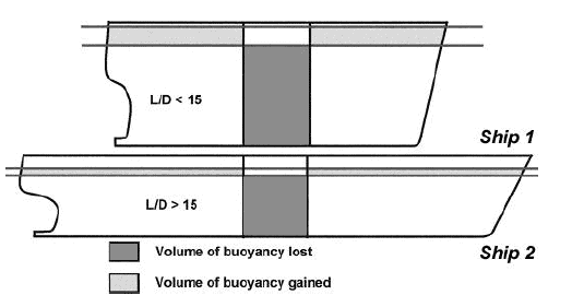
- Correction for Depth (Regulation 31 of ICLL): If the L/D (Length to Depth ratio) of the vessel is less than 15, this means that the depth is high in relation of length. In such case, a damage to a mid-cargo-hold of the vessel will lead to higher loss of buoyancy compared to the standard ship. Thus, vessels with lower L/D ratio than 15 will need an increased freeboard. [Ref 3]
- Correction for Superstructure and Trunks (Regulations 33 to 37 of ICLL): Enclosed superstructure and trunks of a specified minimum height (called standard height) contribute to the reserve buoyancy. The ‘standard ship’ has no superstructure, and if a vessel does have them, their contribution to reserve buoyancy should lead to a reduction in the freeboard. Regulations 33 through 37 of the ICLL provide the detailed basis of qualifying which superstructures and trunks can be considered for freeboard deduction, and also how to calculate their contribution.
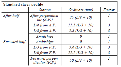
- Correction for Sheer Profile (Regulation 38 of ICLL): Ships with sheer have curved raised decks at the fore and aft ends. This is an important item that contributes to the reserve buoyancy. The ‘standard ship’ has a sheer profile called the ‘standard sheer profile’ as shown below. Ships with a sheer profile with ordinates higher than the ‘standard sheer profile’ will obviously contribute positively to the reserve buoyancy and will get a freeboard deduction. However, a ship with no sheer, or with a sheer lesser than the standard sheer will have its freeboard increased [Ref 3]
- Correction for minimum Bow Height (Regulation 39 of ICLL): Every vessel needs to maintain a minimum bow height at the summer load line. The minimum bow height formula is specified in Reg 39 of ICLL. It is to be noted that Reg 39 was updated in 2003 and the formula too has been updated. Ships that don’t pass the minimum bow height required will have a deduction in their freeboard so that the minimum bow height is assured.
The loadline mark
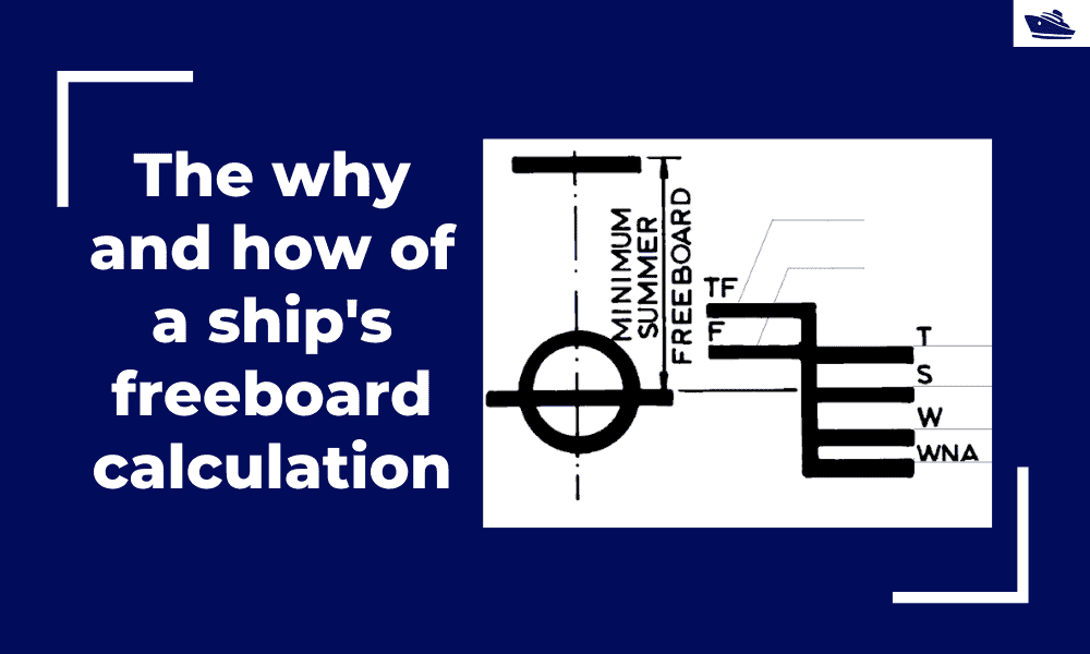
From the above process, the Summer freeboard of the vessel can be calculated. The summer freeboard is used to calculate the summer loadline of the vessel. The Summer Loadline is marked on the vessel as a ‘Loadline Mark’. It is indicated by the upper edge of the line which passes through the centre of the ring and also by a line marked S.
There are multiple other loadlines of the vessel, depending on its area of operation. For sailing ships, only the Fresh Water and Winter North Atlantic loadlines are to be shown, apart from Summer Loadline. These additional lines are:
- The Winter Load Line indicated by the upper edge of a line marked W.
- The Winter North Atlantic Load Line indicated by the upper edge of a line marked WNA.
- The Tropical Load Line indicated by the upper edge of a line marked T.
- The Fresh Water Load Line in summer indicated by the upper edge of a line marked F. The Fresh Water Load Line in summer is marked abaft the vertical line. The difference between the Fresh Water Load Line in summer and the Summer Load Line is the allowance to be made for loading in fresh water at the other load lines.
- The Tropical Fresh Water Load Line indicated by the upper edge of a line marked TF, and marked abaft the vertical line.
That brings us to the conclusion of this article. We have explained all the considerations in calculating the freeboard, and also explained why each of them is needed. Hope this was of use to you. Please do spend some time in exploring our product on Freeboard calculation: FBD the freeboard calculator
References
- International Convention on Load Lines, 1966, as Amended by the Protocol of 1988 – Annex I – Regulations for Determining Load Lines
- DNV Rules for Classification of Ships, Part 3, Ch 5, Loadline
- Unnamed document, CLASS 2/1 STABILITY – SECTION 26 – Calculation and assignment of freeboard (https://web.itu.edu.tr/takinaci/Comp_Progs/Fribord/CALCULATION%20AND%20ASSIGNMENT%20OF%20FREEBOARD.pdf)
- RESOLUTION MSC.143(77) (adopted on 5 June 2003) AMENDMENTS TO THE PROTOCOL OF 1988 RELATING TO THE INTERNATIONAL CONVENTION ON LOAD LINES, 1966
Disclaimer: This post is not meant to be authoritative writing on the topic presented. thenavalarch bears no responsibility for the accuracy of this article, or for any incidents/losses arising due to the use of the information in this article in any operation. It is recommended to seek professional advice before executing any activity which draws on information mentioned in this post. All the figures, drawings, and pictures are property of thenavalarch except where indicated, and may not be copied or distributed without permission.
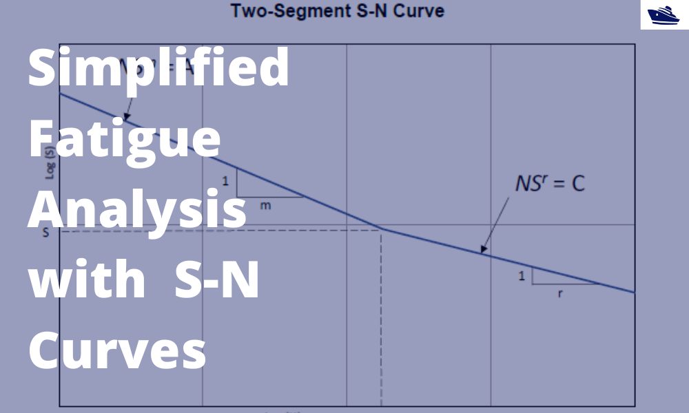
A simplified method of performing fatigue analysis of offshore structures
A simplified method of performing fatigue analysis of offshore structures Introduction An offshore structure is subject to environmental loads of waves, wind and current. By their nature, the resulting wave loads on the structure are cyclical. These cyclical...
How to use a ship’s hydrostatics to calculate its draft and trim
Introduction A ship’s hydrostatics, or hydrostats, is an oft used term in maritime parlance, and it refers to the characteristics when it is floating. What characteristics are these? How are these determined, and how can we read and understand them? Understanding...
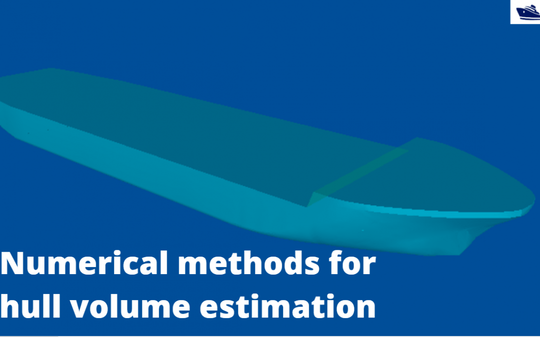
Numerical integration methods for hull volume estimation
Introduction The hull of a ship is a complex 3D geometry, and finding out its simple properties like volume, centroid, etc. is not possible through simple formulae unlike standard shapes like cuboid or a cylinder. How do we find a property, say the volume of a...
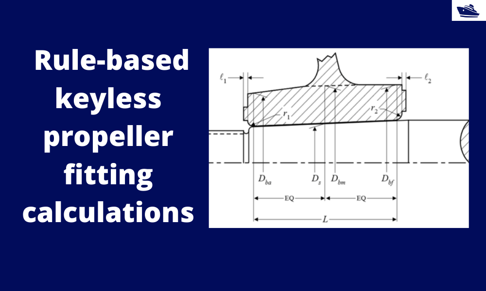
How to do rule-based fitting calculations of a keyless propeller
Introduction A keyless propeller, as the name implies, requires no key for fastening the propeller on the cone of the propeller shaft. How is the torque then transferred to the propeller? The torque is transferred by the friction between the propeller and the...
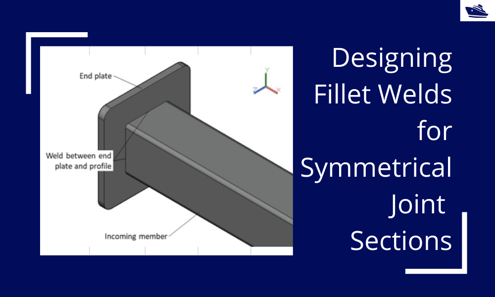
Designing Fillet Welds for Symmetrical Joint Sections
Introduction Fillet welds are the most commonly used weld types in marine structures. A fillet weld is used when there are two pieces of metal that are joined perpendicular to each other or at an angle. In this article, we will explore how to select the right size...
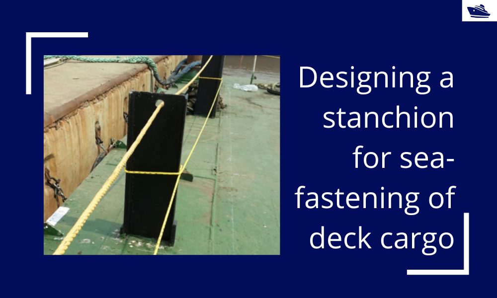
Designing a stanchion/stopper for sea-fastening of deck cargo
Introduction Stanchions – a familiar term for mariners and ship designers. What are Stanchions? A stanchion is generally a vertical pipe or beam which is used to support some structural item or provide support rails on the deck. In ships, the most common type of...
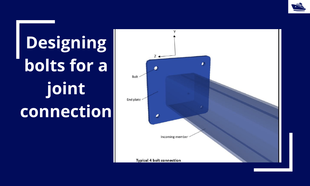
Designing bolts for a joint connection
Introduction Bolts are very commonly used fastening items and used in a variety of configurations. In this article, we will explore in-depth the design of a bolt used in connecting two members at a joint (bolted joint). We'll see what properties of the bolt are...
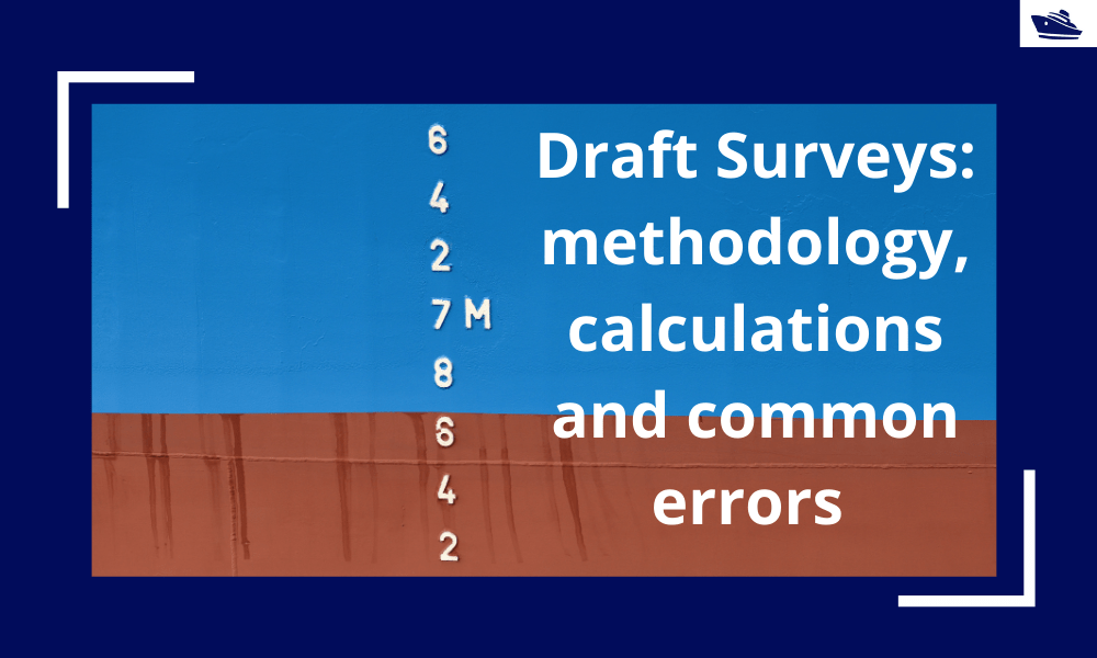
Draft Surveys: Methodology, Calculations, and common errors
Introduction Marine transport is the backbone of the global trade and reasonably can be considered to be the artery of the global manufacturing supply chain, as more than four fifths of the world merchandise trade by volume is carried by sea. Undoubtfully, the...
The Bulbous Bow – types, characteristics, and effects
This is Part 2 of the two-part series on Bulbous Bows. For Part 1, click here By Tamal Mukherjee, *This article originally appeared in May 2019 edition of Marine Engineers Review (India), the Journal of Institute of Marine Engineers India. It is being...
Using Class Rules to assess the Longitudinal Strength requirement of Barges
Introduction The longitudinal strength of a vessel is integral to its evaluation for a given purpose. To get an introduction to the topic, please refer to our other article https://thenavalarch.com/longitudinal-strength-ships-introduction/ In this article, we’ll see...



Impressive♥️⛴
need to know how assign FB for ship without deck
Hi Lassad
That will require us to take a closer look. Can you help send more details to info@thenavalarch.com? Thanks
sorry but nothing to read??
There is nothing to read
Hola soy nuevo aquí, y quería hacer una pregunta,sobre como calcular la manga de un barco para construir a Scala,si es que va relacionado con la eslora para saber el ancho que hay que darle para la flotabilidad