By Alan Crowle, BSc, MSc, CEng, CMarEng, FRINA, FMAREST, FSCMS Masters by Researcher, University of Exeter, College of Engineering, Mathematics and Physical Sciences, Renewable Energy Group
SUMMARY
Floating wind turbine construction is a large logistical exercise. The naval architecture requirements are described for a semi-submersible substructure. Large heavy transport vessels are required to transport the substructures from the shipyard to the fit-out quay. Specialized cargo ships transport turbine blades and nacelles from the dockside factory to the fit-out quay. General cargo ships move the anchors and associated equipment to the mooring assembly yard. The transport vessels for the substructure may be powered, Heavy Transport Vessels (HTV) or non-powered cargo barges. Intact stability, both GM and GZ curves, and damage stability need to be considered. This article outlines the loadout, ocean transport and float off restrictions of the substructure.
The article discusses the naval architecture requirements for transport vessels and will discuss intact stability, damage stability, motions, accelerations, bending moments, and sea fastenings. Constraints such as local width, overhead cables, bridges, and water depths are considered.
The floating offshore wind turbine consists of a lower part, which is anchored to the seabed and an upper part consisting of a tower, the tower generator and the blades. The substructure and upper part are connected together at the fit-out yard using large onshore cranes.
LOADOUT
Loadout is the movement of Cargo from a construction yard onto a transport vessel.
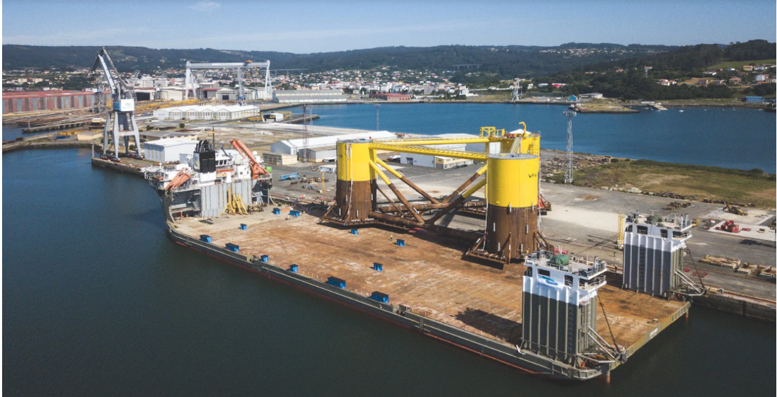
Figure 1 Loadout of semi-submersible onto a heavy transport vessel (courtesy Principle Power)
Input requirements are for the loadout quay are:
- Loadout method Skidding, Self-Propelled Modular Transporter(SPMT) or Lifting
- Quay height above lowest astronomical tide (LAT)
- Water depth at the loadout quay relative to LAT
- Tidal range, Highest astronomical tide (HAT) to LAT
- Mooring bollards on the quay
- Mooring winches on the quay
- Lightship weight and centre of gravity (COG)
Input requirements are for the ocean transport vessel are:
- Cargo weight and Centre of gravity (COG)
- Upper grillage weight and COG
- Ballast tank arrangement
- Ballasting method can either be using vessel pumps or external ballast system
- Mooring bollards on the transport vessel
- Lightship weight and COG
Loadout stability criteria are:
- Transport vessel stability has to be adequate throughout the loadout operation.
- Loadout minimum GM is to be 0.15m but a more realistic minimum GM of 1.0 m is expected
- A loadout check if a small heel or trim occurs as the cargo transfer is completed
- Cases where a change of wind velocity may cause a significant change of heel
- During a loadout other marine traffic is kept away, thus minimizing the possibility of collision
- The under keel clearance is at least a minimum of 1.0m,
- Freeboard to be more than 0.5m plus 50% of the maximum expected wave height
- If the load line is exceeded, confirm it is acceptable by the transport vessel’s class society be
- Normally there is no requirement to document damage stability during loadout.
- Check how incorrect operation of the ballast system may influence stability.
OCEAN TRANSPORT
Input requirements during ocean transport:
- Cargo weight, COG and radii of gyration
- Upper grillage weight, COG and radii of gyration
- Lower grillage weight, COG and radii of gyration
- Sea fastenings weight, COG and radii of gyration
- Ballast tank arrangement
- Ballasting methods
- Minimum water depth on the ocean route
- Air draft restriction, bridges and power cables
- Width restriction, locks and canals
- Lightship weight, COG and radii of gyration
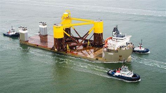
Figure 2 Ocean delivery voyage of a semi-submersible substructure (courtesy Principle Power)
Ballasting
The following constraints are considered:
- Ensure sufficient intact and damage stability
- Trim angle is less than 1%
- Heel angle is zero
- Minimize motions and accelerations on the cargo by weather routing
- Longitudinal shear forces and bending moments are within allowable
- Local strength is acceptable by using grillage to spread the loads from the cargo
- Minimize powering requirements for HTV or the towing tug
- The GM is to include free surface effects and typical values
Intact Stability
The transverse metacentric height (GM) is preferably 1.0m, at zero angle of heel. Correction to values of GM to allow for free surface effects is to be included in this calculation. The application of free surface corrections to reduce metacentric height (GM) and hence to increase natural roll period will not generally be accepted.
The intact stability, or intact range of stability, is the range between 0º heel or trim and the angle at which the righting arm (GZ) becomes negative. The wind velocity used to compute the wind heeling moment curve should be the 1-minute sustained wind for the operation with appropriate return periods. The duration is the tow time that determines the value of the wave height to be used for the motions analysis. The default return period is 10 years return period.
![]()
Table 1 Voyage duration for wind and wave estimation
For barge ocean tow the following motions can be used in the absence of model tests or motions analysis
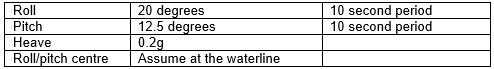
Table 2 Default barge motions
For a self-propelled heavy transport vessel motions are expected to be less and will depend on
- Shape of underwater hull
- Are bilge keels fitted
- Use of weather routing to avoid storms
- Does the vessel have approved heading control, so roll motions can be reduced
Damage stability
As a minimum, the transport vessel should have sufficient stability and reserve buoyancy to remain
afloat at a waterline below any opening where progressive flooding may occur with any one compartment adjacent to the sea flooded. Damage to any compartment above the intact waterline that can lead to loss of stability is considered when assessing damage stability. The loss of water from a full compartment is considered if it gives a more severe result than the flooding of an empty compartment.
Allowable VCG curve
The allowable VCG curve combines the requirements of intact and damage stability.
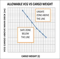
Figure 3 Typical allowable VCG curve
FLOATOFF
Input requirements are during float off:
- Cargo weight, COG
- Upper grillage weight, COG
- Lower grillage weight, COG
- Sea-fastenings weight, COG
- Ballasting methods
- Minimum water depth at the installation
- Under keel clearance
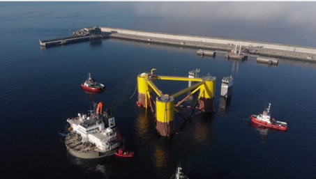
Figure 4 Float off semi-submersible substructure (courtesy Principle Power)
Transport vessel stability criteria has to be adequate throughout the float off installation operation:
- Minimum expected GM 1.0m, including free surface effects
- Low wind velocity and small waves
- For this short term case only intact stability need be considered
- Down flooding points should be above wave crest heights after allowing for run-up.
- It is assumed that there is always 1.0m of under keel clearance during all stages of float off.
COMPLETED STRUCTURE
The completed structure is towed offshore with tugs
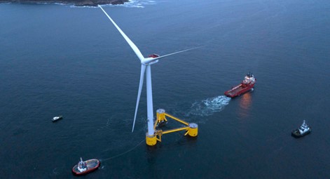
Figure 5 Semi submersible with turbine tow out (courtesy Principle Power)
The stability criteria for the completed structure during tow out are:
- Minimum intact GM of 1.0m
- Intact range of stability of 36 degrees
- Positive freeboard of at least 3m following damage to any single compartment
CONCLUSIONS
The large substructures required for floating offshore wind turbines require large submersible heavy vessel or submersible barges for the loadout, transport and float off.
The transport vessels have buoyancy tanks at both ends so that they van submerge for the float off of the floating offshore substructure. The loadout takes places in good weather at sheltered shipyard location. The float off takes place close to the fit out quay.
ACKNOWLEDGEMENTS
Alan Crowle thanks his colleagues at the University of Exeter for their assistance in preparing this paper and in particular for the assistance of Professor PR Thies.

He has a BSc in naval architecture and shipbuilding from the University of Newcastle upon Tyne (1974) and MSc in engineering for marine professionals at the University of Plymouth (2020). He has over 51 years experience, in the design, construction and offshore installation of marine structures. His work includes jackets, modules, FPSOs, semisubmersibles, loading buoys, LNG terminals and nearshore pipelines. He has renewable energy experience of fixed offshore wind turbines, met masts and high voltage direct current platforms. He is a fellow of RINA, IMAREST and SCMS

for my understanding the floater loadout method