Introduction
Lashing of a deck cargo on a ship involves different means and mechanisms to secure the cargo to the deck of the ship. This ‘securing’ is important to contain the movement of the cargo in view of the ship motions during the transportation.
The simplest ‘system’ which comes to the mind is to take a few ropes and tie one end of each rope to some point on the cargo, and tie the other end to some point on the ship’s deck. The ropes can be evenly distributed so that the securing in all the directions is ensured.
In this article we’ll discuss the basics of cargo lashing and will also take a look at a simple 4-point lashing system design for a rectangular shaped cargo.
Designing the right lashing for a cargo depends on multiple factors
- Size and weight of cargo – a bigger, heavier cargo requires stronger lashings. Also, the available space for lashing is an important factor in deciding the lashing configuration
- Forces on the cargo – depending on the size of the vessel and the environment of the tow route, the cargo experiences forces of surge, sway and heave which lead to pitch, roll and heave forces which need to be overcome by the lashings
- Force distribution – another very important factor is the distribution of forces among the lashings used. The forces should be evenly distributed among lashings, and there should not be a possibility of a lashing getting slack or another getting overloaded.
- Protection against sliding – generally if the friction force is not enough to protect against sliding, then dunnage can be utilized for increasing friction. Lashings should be able to provide sufficient restraint against sliding. Alternatively, stoppers can be used in conjunction with lashings
- Protection against tipping – the lashing design must also provide protection of the cargo against tipping when the vessel rolls/pitches.
Four-point lashing design for a rectangular shaped cargo
A Cargo in the sea will experience forces of surge and sway in the longitudinal and transverse directions, and heave in the vertical direction.
The lashings should be sufficient to resist the transverse forces from either Port or Starboard sides, and also to resist the longitudinal forces from fwd/aft.
Since there are restraints to be provided in four directions, we can imagine a simple system consisting of four lashings are shown in figure below:
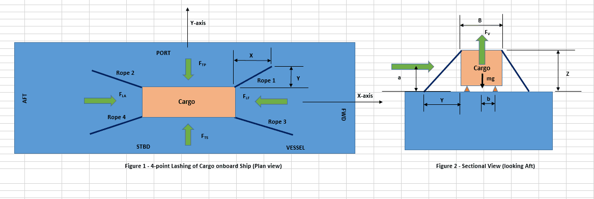
We can infer from the above figure that
- The longitudinal force aft is restrained by Lashings 2 & 4
- The longitudinal force fwd is restrained by Lashings 1 & 3
- The transverse force PORT is restrained by Lashings 1 & 2
- The transverse force STBD is restrained by Lashings 3 & 4
How much of a load a particular line will be able to take up in a given lashing configuration depends purely on the location of the line, its length and the angles it makes relative to the vertical and horizontal planes.
The basic outline of the whole method is:
- Calculate the total restraining forces + friction forces in a particular direction
- Check if the total restraining force in that direction is more than the external force
- If yes, then lashing is adequate
- If no, then consider reconfiguring the lashings – change size or strength of lashings and check again
We take an example of the transverse sliding force on the port side.
- We can see that the Ropes 1 & 2 are restraining the port side transverse force
- The restraining force available from each rope is not the full MSL (Maximum Securing Load) of the rope. A rope at an angle of θ to the horizontal will be able to provide a restraint of only R = MSL x cos(θ) in the horizontal direction (See figure below). The MSL is further reduced by a factor of 1.5 as per IMO CSS.
- The restraining forces of each of the ropes 1 & 2 is calculated depending on their orientation in the lashing design. The factors for calculating the restraining forces are provided in IMO CSS, depending on
- Angle of rope with vertical
- Angle of rope with horizontal
- Coefficient of friction between cargo and deck
- If the restraining forces available from the ropes 1 & 2 is F1 and F2, respectively, and if the frictional force on the cargo is Ffric, then the total restraining force available in the transverse direction (Port side) is
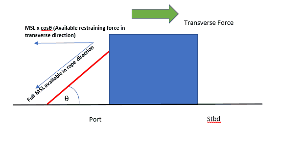
Available restraining force from a lashing
R = F1 + F2 + Ffric
- If the total transverse force on the port side is FTP, then R must be greater than FTP for the lashing design to be adequate.
FTP < F1 + F2 + Ffric
Such sliding check shall be done for sliding in all the four directions
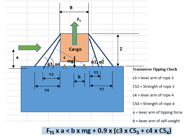
Tipping check
The cargo is also prone to tipping at the edges. To demonstrate sufficient restraint against tipping, the levers of the lashing forces are also taken into account and it is to be demonstrated that the total restraining torque available from the lashings is more than the total tipping moment caused by external forces. The self-weight of the Cargo also provides restraining torque against tipping. Generally, tipping is critical only in the transverse direction if the cargo is oriented longitudinally. The figure below demonstrates this
Following the above method based on IMO CSS, we can design a simple four-point lashing system for simple cargoes. For any failure in the lashings, the design parameters and/or lashing sizes can be changed to arrive at a design which is adequate.
TheNavalArch has its own app for 4-point lashing design based on IMO CSS. Do check it out here:
References:
- “Guidelines for the Preparation of the Cargo Securing Manual” (IMO MSC/Circ.745)
- “Amendments to the Code of Safe Practice for Cargo Stowage and Securing (IMO MSC/Circ.1026)”.
-
Bollard Pull Calculations for Barge
$49.00 Add To Cart -
Bollard Pull Calculations for Ships
$79.00 Add To Cart -

Cargo Forces & Accelerations – Open Ocean
$49.00 Add To Cart -

Pipe Stacking Height Calculator (Bare Steel Pipes)
$39.00 Add To Cart -

Pad-Eye Design Spreadsheet
$49.00 Add To Cart -
Stopper Design Spreadsheet
$49.00 Add To Cart -

Bollard Strength Check Spreadsheet
$39.00 Add To Cart -
Ship Squat Calculator
$49.00 Add To Cart -

Towing Bridle Design Spreadsheet
$39.00 Add To Cart -

Stanchion Design Spreadsheet
$49.00 Add To Cart -

Towing Bridle Force Calculator
$29.00 Add To Cart -
Lashing Design (4 Point Lashing, IMO CSS)
$49.00 Add To Cart

you got already my email ane as I subscribed to your list
Does the acceleration criteria of the ship or barge be taken into account for this calculation?