A vessel at berth experiences much lower forces compared to a vessel in the open sea due to the milder environment, but it still requires a mooring configuration suitable to the forces it experiences, and also suitable for the type of berthing configuration adopted. The berthing configuration depends on the geometry of the berth, and also on the available space depending on the traffic at the berth and size of the vessel. Two berthing configurations which are mostly used are:
- Configuration 1: with the vessel’s Stern aligned with the Quay
- Configuration 2: with the vessel’s Port or Starboard side aligned with the Quay.
Both these configurations are shown in the sketches below.
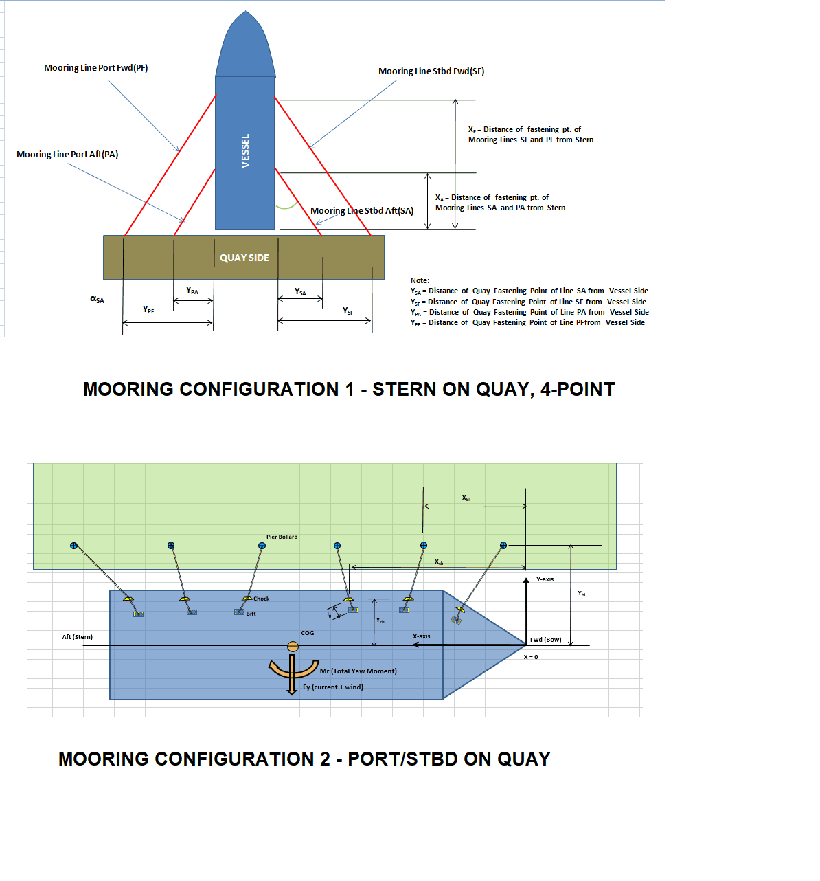
Figure 1 – Two different mooring arrangements at Quay
Concept
For each configuration, the mooring design has to be adequate to restrain the forces which the vessel experiences. In this article, we will analyse the first configuration – the Stern on Quay in more detail, and present a simplified method for calculating the line loads for a 4-point mooring pattern with the vessel’s Stern on Quay.
The Stern-on-Quay configuration can be used when there’s limited space available for the Port-on-Quay configuration, or when specialized operations like loadout are needed. During these operations, it is important to hold the vessel in place when the loadout operation is being carried out. The vessel will be subject to external forces of wind, current and wave, and so it is important to design a mooring system which can overcome these forces.
Thinking in very basic terms, the vessel will have its Stern pressing against the Quay (with fenders between the vessel and Quay to take the load). This vessel will be subjected to environmental loads coming from the beam side of the vessel (athwartship) which will tend to drift it off. A simple way is to tie the vessel to the quay side using ropes, and the simplest solution is to use a rope on each side, running each from the Port or Starboard side of the vessel, and tied to a bollard on the Quay. However, this simplest solution, while feasible, doesn’t have any backup in case the rope on either side breaks. Also, if the ropes are tied closer to the fwd end of the vessel, the aft end may be subjected to an undesirable yaw moment. Thus, a safer and more recommended solution is to have two ropes on either side, running to different bollards on the Quay Side. This ensures that the entire load is distributed over two ropes on either side.
The next step will be to find out what line size and strength will be required to moor a vessel. The entire concept can be delineated in the following steps:
Calculation Steps
- Get the vessel’s dimensions and cargo dimensions
- Get the environmental parameters of the Quay – Wave height, wind speed and current speed
- Calculate all the environmental forces on the vessel from the beam side (either port or Starboard). Also calculate the location along the length of the ship where the net force acts.
- It should be noted here that while current and wave forces can be considered to be acting at the longitudinal centre of floatation of the vessel (which is close to midship), the point of application of wind force will depend on the size and location of cargo (if any) along the length of the vessel.
- For a conservative analysis, the forces are considered to be collinear, i.e., all forces acting at the same time along the same direction
- Using basic physics formulae, balance the mooring line tensions against the force and moment due to the force. Here, the moment arm is the distance of the net force from the Quay.
- There are two sets of equations – one balancing the line tensions against the net environmental force, and the other balancing the moments.
- The combination of the above two equations gives the lie tensions on the lines on either side. It is assumed that the lines are non-elastic
Environmental Forces
When calculating the wind and current forces, the standard physics formula of Force = Pressure x Area shall be used.
For wind force, the formula is Fwind = 1/2 x ρwind x Vwind2 x Awind, where ρwind is the density of air, Vwind is the wind speed, and Awind is the total area of ship and cargo which is exposed to the wind from beam direction (the above-water area)
Similarly, for current force, the formula is Fwind = 1/2 x ρwater x Vcurrent2 x Aunderwater, where ρwater is the density of water, Vcurrent is the current speed, and Aunderwater is the total underwater area of ship which is exposed to the current from beam direction.
The exposed areas to current and wind are shown in the figure below:
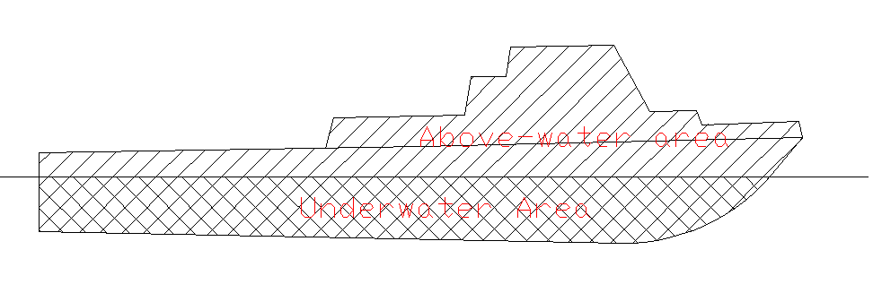
Figure 2 Mooring-Stern-on-Quay-Wind-and-current-areas (above water area includes hull, cargo and superstructure)
The Wave force is the additional wave load (Wave Drift Force) which will arise due to the harbour waves which the vessel experiences. Though the wave heights at Quay are generally low, this force whould also be considered. These are related to wind speeds, and high wind speeds may lead to significant wave heights as well. Please see below Beaufort scale to get the idea of relation between wave height and wind speed:
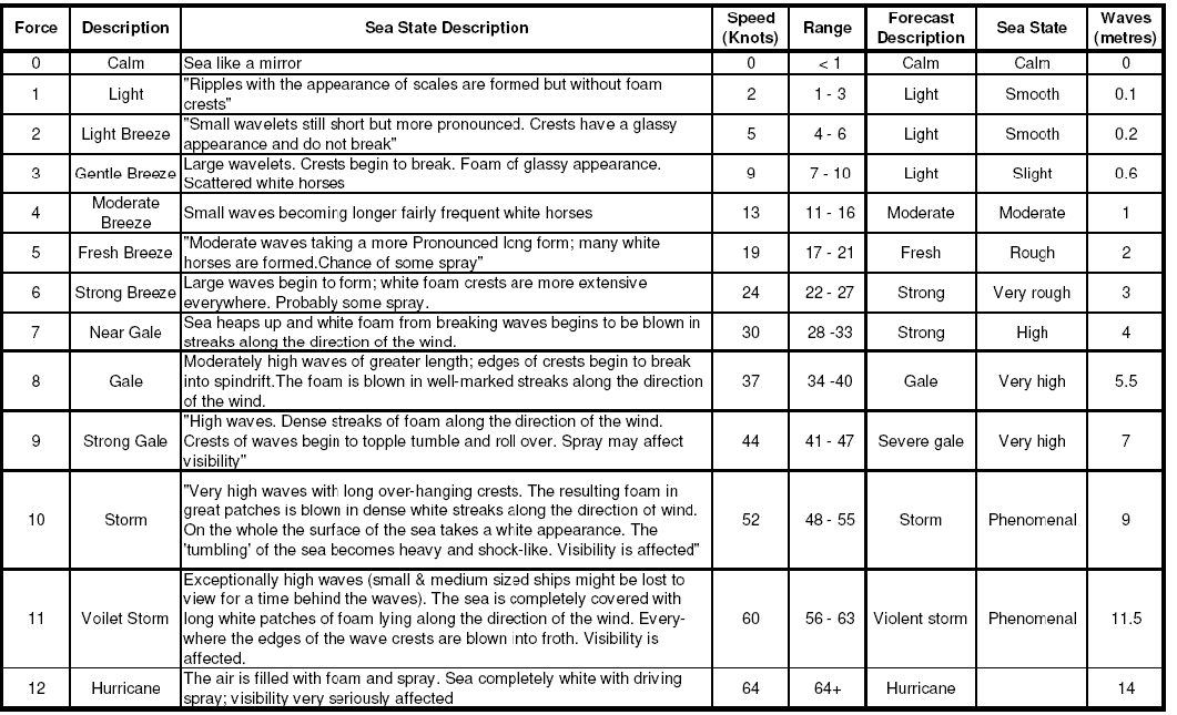
Figure 3 Beaufort-Scale
The Wave drift force can be calculated from DNV-RP-H103, Sec 7.2.6, taking the reflection coefficient R as 1. L is ship’s length and HS is the significant wave height.
FWD = 1/8 *ρwater*R2*L*HS2
Line Force Calculation
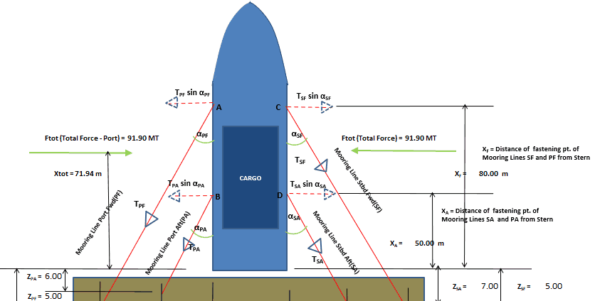
Once the forces have been calculated, the calculation of the line forces on the mooring line on either side can be done using the two equations of balance of forces, and balance of moments. The calculations based on TheNavalArch’s own App, are shown below:
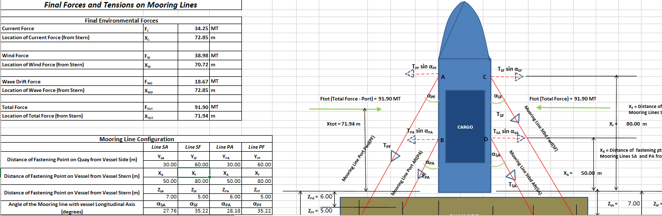
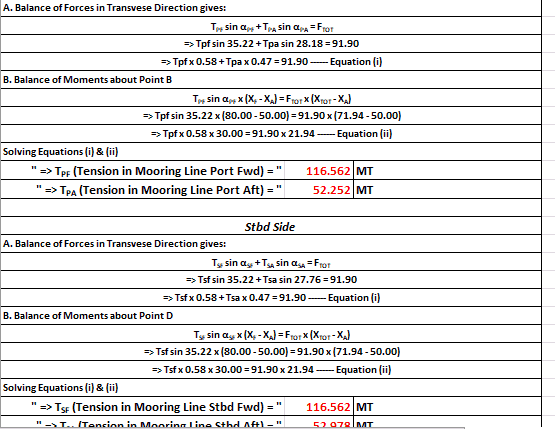
Figure 4 Sample calculations for 4-point, Stern-on-Quay mooring arrangement
The above simple method can serve as a quick check to help design a simple 4-line mooring pattern for vessels moored with their Stern on Quay. However, if high accuracy is demanded, or if multiple cases of environment from different directions are to be investigated, then a full fledged mooring analysis can also be carried out using standard software like Orcaflex (you may contact us for the same). For simple cases, the above calculation should suffice.
Please do take a moment to explore our own excel-ased App which performs the above detailed calculation. With simple user interface and basic inputs, it performs a quick assessment of the line loads and presents a basic mooring plan.
-
Mooring Forces Calculator (Stern on Quay, 4-Point Mooring)
$99.00 Add To Cart -
Mooring Forces Calculator (Port or Stbd on Quay)
$99.00 Add To Cart -
OCIMF Environment Forces Calculator – Tankers (Updated toMEG-4)
$99.00 Add To Cart -

OCIMF Environment Forces Calculator – Gas Carrier (updated to MEG4)
$99.00 Add To Cart -
Capstan Design (Required power for Berthing)
$49.00 Add To Cart -
Cargo Forces & Accelerations – Open Ocean
$49.00 Add To Cart -
Mooring Line Catenary App
$99.00 Add To Cart -
Motion Response Calculator
$99.00 Add To Cart -
DNV Ship Motion Calculator
$99.00 Add To Cart -
OCIMF Anchoring Environment Loads Calculator
$99.00 Add To Cart -
IMO Based Risk Estimator
$99.00 Add To Cart -
Fishing Vessel Equipment Number Calculator
$39.00 Add To Cart

Very good information for me concerning mooring design & analysis