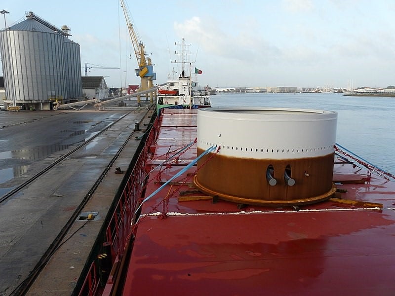
A cylindrical deck cargo (Source: Wikimedia)
Introduction
A ship’s deck is used to transport many different types of cargo – from containers to large structures like cranes or heavy modules of an offshore production plant. During transport, the ship suffers from forces due to the environment (wind, wave, current) it encounters. Being on the ship’s deck, the cargo also encounters these forces. For the cargo to be stable while being subjected to these forces, it is to be secured to the deck of the vessel using means like lashing ropes, stoppers, beams etc. This is called the ‘Seafastening’ of cargo.
Thinking backwards from the final goal of restraining the cargo, we need to know the forces on the cargo to design seafastenings. To know the forces on the cargo, we need to study the forces on the ship. To get the forces on the ship, we need to know the environmental parameters (wind, wave current) which the ship operates in. These parameters depend on the ship’s voyage route.
Thus, the simplified approach is:
- Step 1: Find out the environmental parameters
- Step 2: Find out the forces suffered by the ship in the environment
- Step 3: Find out the forces on the cargo due to the ship’s motion
- Step 4: Design the seafastenings to restrain the cargo forces
We will take the above steps one by one and elaborate on them.
Step 1 – The Environment
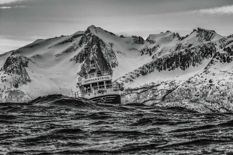
Figure 2 – A ship in waves (Source: pixabay)
The environment of the voyage can be Unrestricted, or Restricted. Weather restricted operations are generally in sheltered areas or coastal regions where wind, wave and current are expected to be milder compared to the ‘Open Ocean’ where the weather is ‘unrestricted’.
The environmental data can be obtained from detailed Metocean data of the tow route proposed. This gives us the design wind speed, wave height and current speed for which we need to calculate the environmental forces on the vessel.
Step 2 – Forces on the ship
Once we have the environmental parameters with us, how do we calculate the forces which they will exert on the ship?
The ship has six different motions and accelerations, which are shown in the figure below:
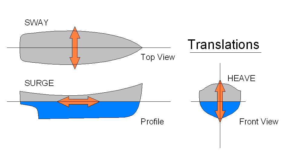
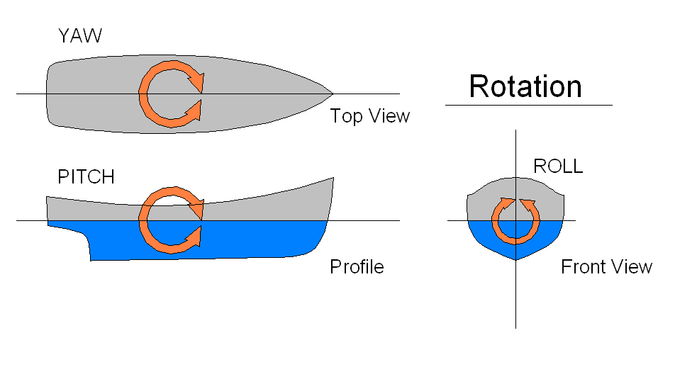
Figure 3 – The six motions of the ship (source Wikipedia)
- Surge – this is the forward/backward motion of the ship, along its length
- Pitch – this is the up and down rotation of the bow or stern of the ship
- Sway – this is the sideways motion of the ship, along its width
- Roll – this is the sideways rotation of the ship’s port and starboard
- Heave – this is the movement of the ship up and down
- Yaw – this is the side-to-side rotation of the ship’s bow and stern
Each of the above motions is coupled with an accompanying acceleration. While Surge, Sway and Heave are linear accelerations, Pitch, Roll and Yaw are angular accelerations due to rotatory motion of the ship.
How do we estimate the motions and accelerations (forces) on the vessel?
There are multiple ways of doing the force calculation, depending on the time and resources at hand.
- Model Testing – Tank tests in a basin can be performed on ship model to evaluate the behavior of the vessel in sea, and to provide the design motions and accelerations. However, model tests can be performed only during the design stage of the ship and are also quite costly.
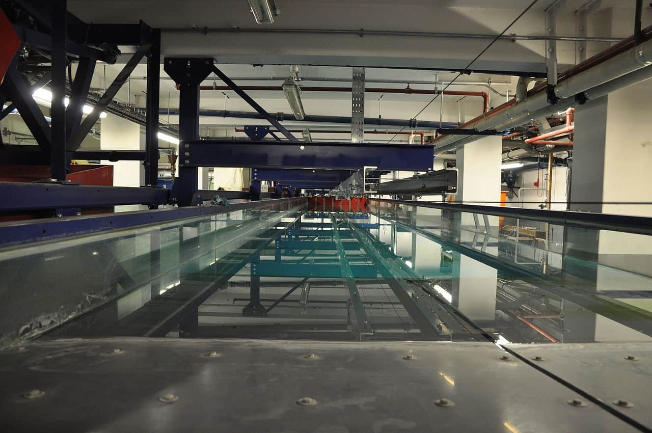
Figure 4 – The Ocean Towing Tank at University College London (source; Wikipedia)
- Motions Analysis – Another method is to perform a detailed motions analysis of the vessel. This is an elaborate process involving preparing a hydrodynamic model of the vessel in a specialized software and applying the environment forces to perform a time of frequency domain analysis to evaluate the forces on the vessel.
- Default Motion Criteria (DNV) – If a detailed motions analysis is not available, there are some default motion criteria which can be used. One such set of criteria are provided in the DNV document DNV-ST-N001 – Marine Operations and Marine Warranty (2016), Sec 11. There are different criteria which can be used depending on the methodology adopted.
- IMO CSS – For smaller cargoes under 100 MT, the IMO Code of Safe Practice for Cargo Stowage and Securing can be used for calculating the motions and accelerations. An excerpt is provided below. These are applicable for ships of length 100 m and speed 15 knots. Correction Factors are applicable for ships of different length and/or speed. These are not applicable for ships less than 50 m or more than 300 m in length.
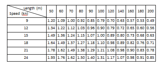
Fig 5: Accelerations as per IMO CSS
- Class Rules – Class Society rules provide the next source for getting motion and accelerations. Different rules are available from DNV, ABS, LR etc. For example, the DNV GL Rules for the Classification of Ships, /36/, Part 3, Chapter 4, Section 3 provide elaborate formulae to calculate the design accelerations for a ship. An excerpt is presented below:
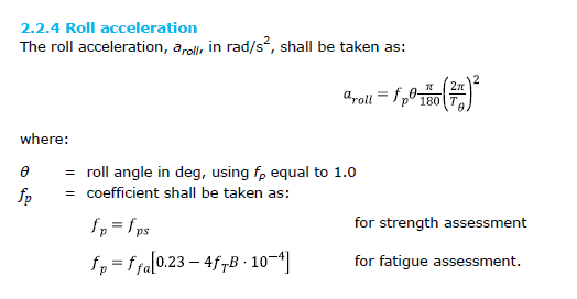
Figure 6: DNV Ship Accelerations Formula for Roll
However, most of the Class rules will provide quite conservative results (based on loads at 10-8 probability level), and they may be too high for an actual marine operation. These results are mostly used for design of the vessel. For marine operations, these accelerations may be reduced using a reduction factor provided in the respective Class Rule. For reduction factors applicable to DNV Class Rules, please see Sec 11.6.3 of DNVGL-ST-N-001.
- Alternative Methods – There are two approaches used:
- The ASD/WSD method – These are based on AISC Allowable Stress Design and provide the Roll & Pitch amplitudes and Heave accelerations for different weather cases and vessel types. These can be found in Sec 11.7.2 of DNVGL-ST-N-001. An extract is presented below:
- The LRFD method – These are based on Load Resistance Factor Design method and provide the accelerations in longitudinal, transverse and vertical directions for standard “North Sea Barge” (300’ × 90’ × 20’) and bigger barges. These are provided in Table 11-2 of DNVGL-ST-N-001. It can also be used for smaller barges with B > 20 m and L > 50 m with normal cargo configurations. An extract is provided below:
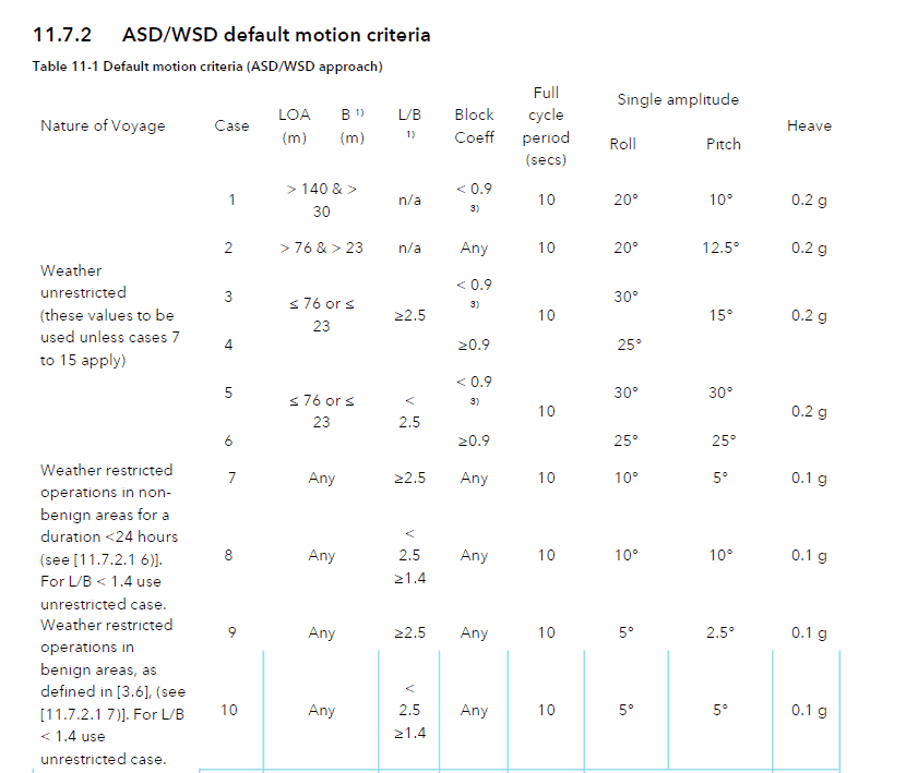
Figure 7: ASD/WSD Default Motion Criteria
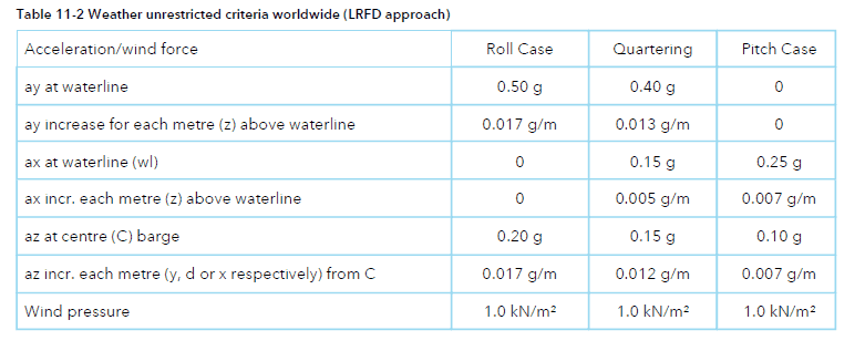
Figure 8: LRFD Default Motion Criteria
Step 3 – Forces on the Cargo
Once the forces on the vessel have been obtained, how to determine the forces on the cargo?
Forces on the cargo depend on multiple factors like the weight and center of gravity of cargo, its location on the deck and its size.
As the ship undergoes motions in the sea, the cargo expects following types of forces:
- Static Forces –
- Self-weight – The self-weight of the cargo is a static force on the cargo.
- Moment of Inertia – for large sized cargoes, the self-moment of inertia of the cargo also contributes to the dynamic roll/pitch forces. This is generally ignored for small sized cargoes.
- Dynamic Forces – These are the forces arising due to the rotatory motions of the ship – rolling and pitching. Basically, any rotatory motion leads to an angular acceleration which adds to the force on the cargo
- Combined Forces – When the ship heaves and rolls/pitches simultaneously, a component of heave contributes to the acceleration in transverse direction too. These kinds of forces are called combined forces.
Resolving the cargo’s forces
When a motion analysis software is being used to calculate the forces on the cargo, then detailed results may be obtained. These analyses will generally be based on a frequency or time-domain analysis which uses a wave spectrum and vessel’s hydrodynamic model to generate vessel Response Amplitude Operators (RAO’s) and provide the accelerations as results.
When Default Motion Criteria are being used, then the following simplified approach can be used to determine the motion forces on the cargo.
First step is to adopt a ship-based coordinate system. This is a coordinate system which is fixed to the ship, and is defined as below:
- The origin of the coordinate system is at the Longitudinal Center of Floatation (LCF) of the ship
- Longitudinal axis is along the centerline of the ship
- Transverse axis is along the port or starboard
- Vertical axis is vertically upwards from the LCF
This coordinate system moves with the ship and is not fixed to the ground. Many times, due to lack of the data on LCF, the midship is used in place of LCF. This may lead to minor difference in results.
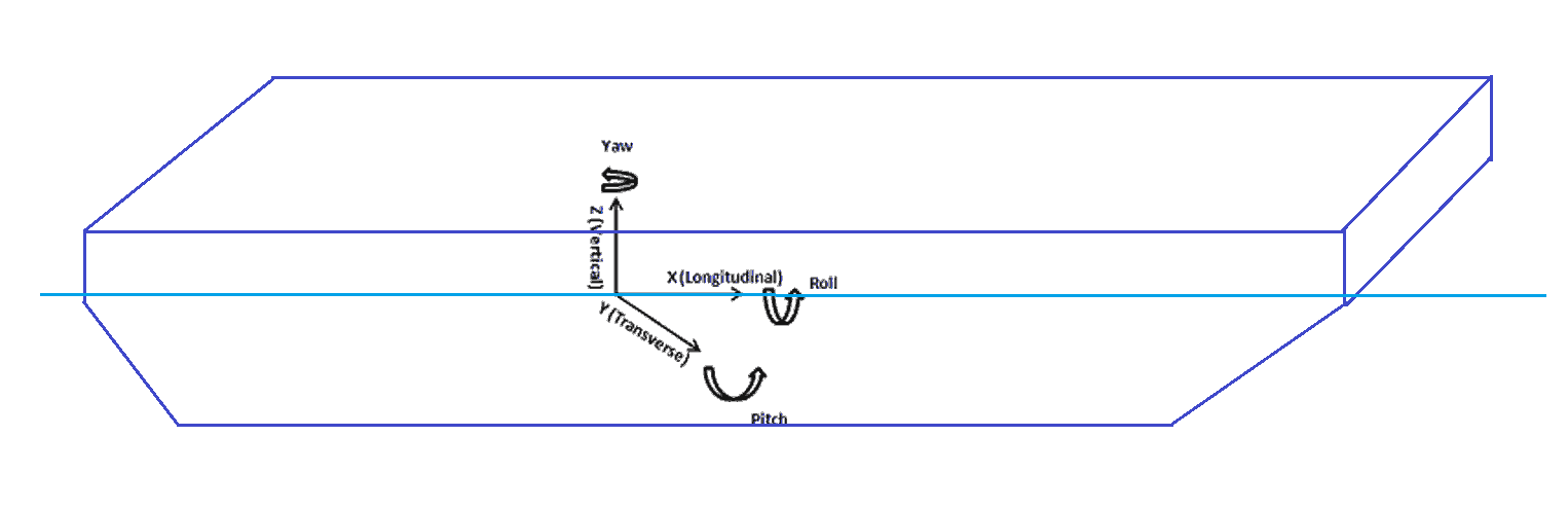
Figure 9: A ship-fixed coordinate system
Next step is the resolution of the forces in different directions – Transverse, Longitudinal and Vertical. A simple presentation of calculation for transverse and vertical forces is shown in the figure below.
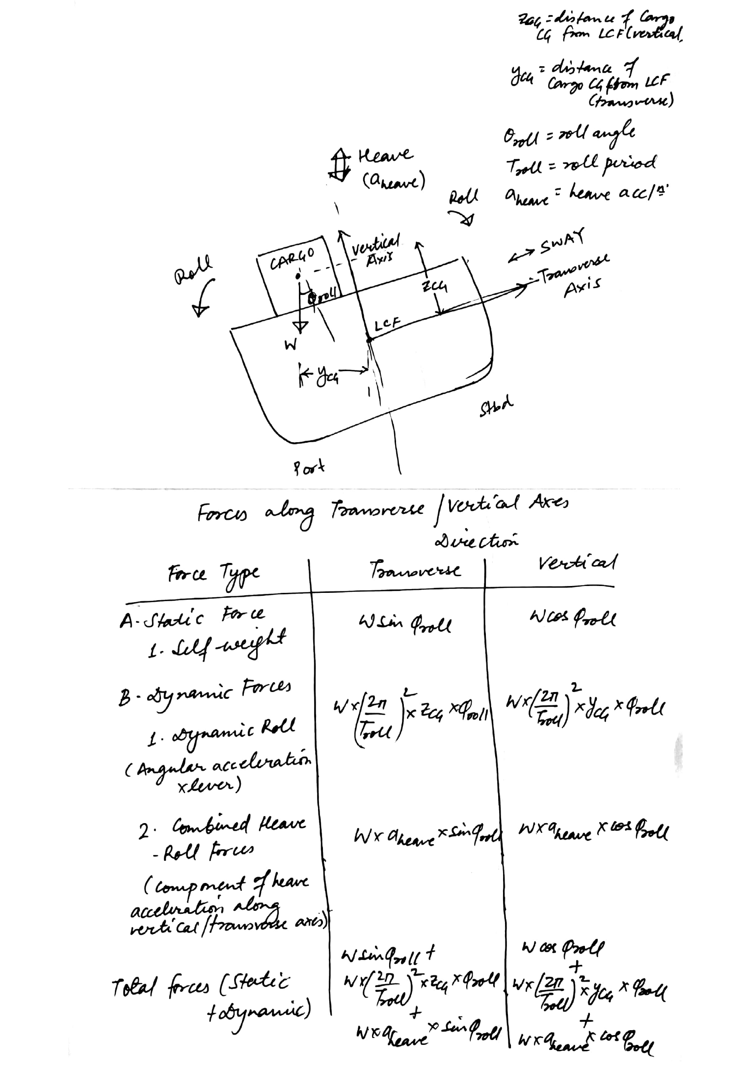
Figure 10: Calculations of Transverse and Vertical Forces
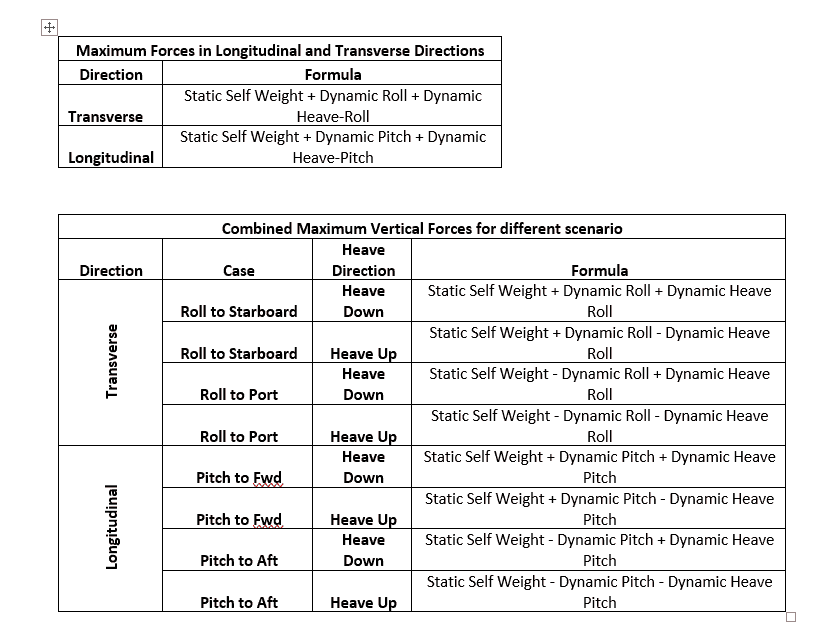
We can see that each force is resolved along the two directions – transverse and vertical in the ship coordinate system. The total force in each direction is calculated by adding up the components. It is to be noted here that the maximum of all components may not happen simultaneously, and there will be phase difference among them. However, ignoring the phase differences will lead to more conservative results.
For forces along the vertical direction, the net force being experienced also depends on the direction of heave or roll. For example, when the cargo is heaving upward, the dynamic heave force in the vertical direction will be opposite to the static self-weight of the cargo and should be deducted in the final force calculations. Similarly, when the cargo is rolling from Port towards Starboard, and considering the positive transverse axis is towards Starboard, then the dynamic roll force in vertical direction will be positive. However, when the cargo rolls from Starboard to Port, then the dynamic roll force in vertical direction will be negative. Similarly, the dynamic heave-roll force in the vertical direction will be positive when the ship is heaving up, and negative when the vessel is heaving down.
The same above scenarios apply to Pitching as well, and the following table summarizes how the final accelerations should be presented.
Wind Forces
Besides the motion forces as discussed above, the cargo will also be subjected to wind forces, which will depend upon its projected wind surface area in both directions, and on its height above the sea level.
Combining the wind and motion forces we can get the final forces on the cargo in transverse and longitudinal directions.
These forces can further be exploited to design the lashing/seafastenings of the cargo.
A simple excel spreadsheet can be developed for performing these calculations. The spreadsheet should take as input the vessel’s properties, the cargo properties and the wind speed as inputs. The motions can be taken from the ASD default motion criteria in DNV-ST-N-001. These can be used to compute the accelerations and forces as described above.
Limitations
Obviously, the above method is highly simplified one and is recommended only when the option of a detailed motions analysis is not available. Some limitations are:
- Conservative results – the values provided in DNV Default Motion Criteria (ASD/LRFD/Class Rules) are based on extreme weather and will give quite conservative results. An actual motions analysis may reveal considerably lower values. As a result, the seafastening design based on these results may be over-designed.
- Self-moment of inertia ignored – The above calculations ignore the self-moment of inertia of the cargo due to its own size and assume the cargo as a point load. This is valid for small sized cargo (relative to the vessel), but for bigger sized cargo (any cargo with length more than one-third of the vessel’s) the forces arising due to self-moment of inertia of the cargo need to be considered.
- Role of phase in force calculation – The different dynamic forces of roll and heave-roll have their own phases and their maximums may not occur simultaneously. This method just adds the maximums to give the final force. This leads to conservative results, and potential over-design of seafastenings.
While above limitations exist, the above method provides a quick check of the forces on the ship and is useful in time-limited demanding operations (when an elaborate motions analysis is not feasible), and in preliminary stages of design when the tolerance for error is more.
References:
DNV Rules for Classification of Ships, Part 3, Ch 4 Loads
IMO CODE OF SAFE PRACTICE FOR CARGO STOWAGE AND SECURING, 2011 Ed.
DNVGL-ST-N001 Marine operations and marine warranty (Edition: 2016-06)
Note: TheNavalArch has its own app for calculation for Cargo Forces and Accelerations. Do check it out in the link below:
-
Bollard Pull Calculations for Barge
$49.00 Add To Cart -
Bollard Pull Calculations for Ships
$79.00 Add To Cart -
Cargo Forces & Accelerations – Open Ocean
$49.00 Add To Cart -
Pipe Stacking Height Calculator (Bare Steel Pipes)
$39.00 Add To Cart -

Pad-Eye Design Spreadsheet
$49.00 Add To Cart -
Stopper Design Spreadsheet
$49.00 Add To Cart -

Bollard Strength Check Spreadsheet
$39.00 Add To Cart -
Ship Squat Calculator
$49.00 Add To Cart -

Towing Bridle Design Spreadsheet
$39.00 Add To Cart -

Stanchion Design Spreadsheet
$49.00 Add To Cart -

Towing Bridle Force Calculator
$29.00 Add To Cart -
Lashing Design (4 Point Lashing, IMO CSS)
$49.00 Add To Cart

Very good informative article. How do you calculate vertical and longitudinal deflection of various decks due to sea waves and how do you arrive at fatigue.
Hi Pankaj
Thanks for your query. Deflection/fatigue require separate analyses best done in a specialized software.
I find this very revealing.
But, sir, I was wondering if I could get a MORE detailed material on this topic, ”CALCULATING FORCES ON A SHIP’S DECK CARGO”