Pad-eyes are one of the smallest and most universally used structural items in the maritime and Oil & Gas industry. They are used for a variety of purposes too: from a simple seafastening of a cargo to deck of a vessel, to complicated lifting operations involving multiple lifting points. Simple as they may seem, pad-eyes vary a lot in their geometry depending on the purpose they are being used for. When they are used for lifting purpose, they are also called as lifting lugs.
The basic purpose of a pad-eye is to provide a point to which a rope or wire can be fastened, directly or through a shackle. The other end of the rope/wire can be fastened to another pad-eye located elsewhere, or it may be used for lifting.
Let’s understand it with an illustration. On ships, the most common purpose of a pad-eye is to fasten a cargo to the deck of the ship. The most common way we can fasten a cargo to deck is to tie it to deck using ropes or wires. The question arises – which point on the deck do we tie it on? What should the connection point look like? Thinking in very basic terms, the connection point should have a slot through which the rope/wire can pass. Also, the connection point should be welded to the deck. The most common connection points used are pad-eyes, as can be seen in the picture below:
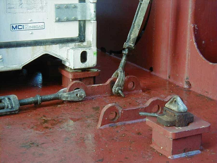
Pad-eye used for lashing cargo to deck
The connection point on the cargo to which the other end of the rope/wire is connected, can also be another pad-eye.
Shape and Size Variations
Size variations for pad-eyes are quite obvious. An operation which imposes higher loads on the pad-eye will require a bigger sized pad-eye. For example, to lift a 1 ton Cargo using single point lifting, the pad-eye size will be much smaller compared to the case with a 10 ton Cargo.
Pad-eye shapes can vary depending on use. When there is only a vertical load expected on the pad-eye (e.g., lifting operations with lifting sling completely vertical), then the pad-eye is generally symmetrical in design. Symmetrical pad-eyes may also be used for sling angles of upto 60 degrees with the horizontal/base of pad-eye. However, if the sling angle with the base of the pad-eye is expected to be less than 60 deg, then an asymmetric pad-eye is recommended.
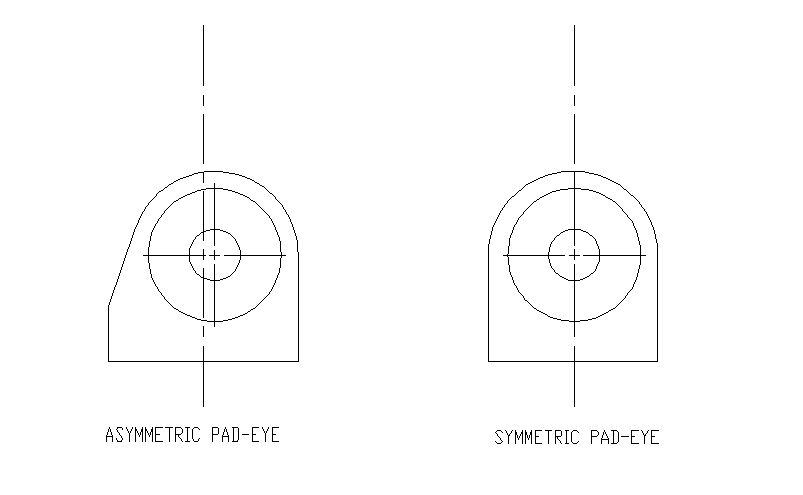
Asymmetric-vs-Symmetric-Pad-eye
A typical design
In this section, we will present a typical design of an asymmetric pad-eye with single cheek plate on either side, used for lashing operation. It looks like the one shown in picture below:
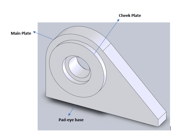
3D view of an Asymmetric Pad-eye
We can see that the pad-eye has three distinctive features:
1. The main plate – this is the asymmetric plate with an eye-hole through which the rope passes.
2. The pad-eye hole – this is the slot through which the wire/rope passes. The size of the hole is determined by the size of the rope which has to pass through it.
3. The cheek plates – not a necessary feature, these are round shaped plates which are welded to the main plate to reinforce the main plate around the hole. The maximum stress region is around the hole, so cheek plates serve to strengthen only this region and save material which would otherwise have been wasted on a thicker main plate. Pad-eyes can also be without cheek plates, and they may also come with two cheek plates on either side.
The base of the pad-eye is generally welded to the item to be lashed against. It can be the deck of the vessel, or it can be the cargo. The base weld of the pad-eye is a critical element in the entire design, and needs to be assessed for the different stresses it experiences.
Following pictures show different pad-eyes with and without cheek plates.
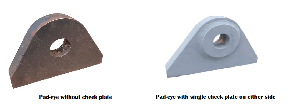
Pad-eyes with and without cheek plate (sources: alphaweld.com.au, lifting.com)
Design Calculations
Let’s now analyze a simple asymmetric pad-eye with cheek plate on either side, and under an external load. A simple figure of the pad-eye with load is shown below:
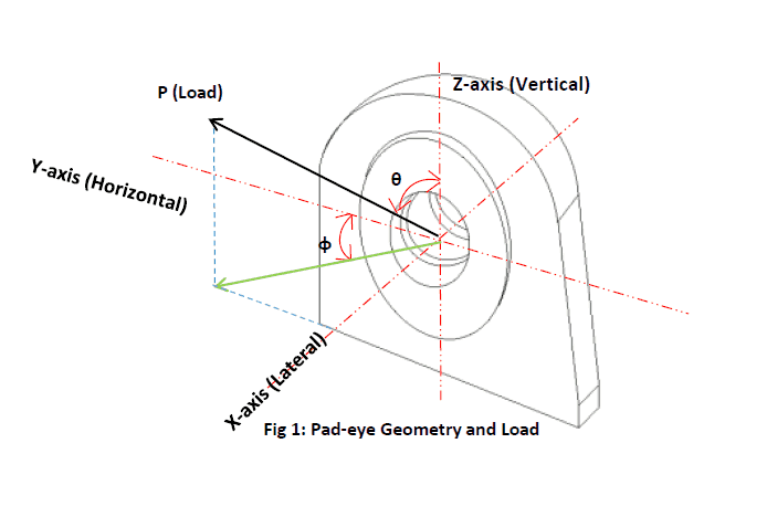
A 3d model of a pad-eye with load
For easily resolving the forces on the pad-eye, we have adopted a 3-dimensional axis system. The horizontal axis is along the length of the pad-eye, the lateral along the width and the vertical along the height of the pad-eye. The origin of the coordinate system is at the centre of the hole. We can see in the picture above that the load on the pad-eye is P, and the load is not along the horizontal axis of the pad-eye. The load is at an angle to both vertical axis (Z-axis) and and the horizontal axis (Y-axis). The horizontal axis (Y-axis) is the weak axis and the lateral axis (X-axis) is the strong axis, and we can see that there is an ‘off-axis’ load on the pad-eye along the X-axis. Considering the off-axis load in the design is quite critical, as it may lead to very high stresses due to bending along the weak axis. Generally, even if the entire load of the pad-eye is expected along the horizontal axis, a rule of thumb to design the pad-eye for at least 10% of the load acting along the lateral axis, or by taking the load acting at an angle of 5 degrees (angle φ in the picture above) to the horizontal axis.
There are different kinds of stresses which different parts of the pad-eye are subject to. Let’s analyze them one by one:
- The Pin Hole – the immediate point of application of the force is the pin hole of the pad-eye. The hole undergoes multiple types of loadings and these cause different stresses. Let’s examine them below
- Bearing Stress: The lashing rope goes through the pad-eye either directly or through a shackle. The diameter of the rope or the shackle will be lesser than that of the hole, and this will create a ‘bearing’ pressure on the hole, as seen in the picture below. The area which is highlighted as the arc of contact between the pin and the hole is the bearing area. The stress is calculated by dividing the pad-eye load by the bearing area
- Shear Stress: The load also causes a pull effect along the surface of cheek and main plates which causes shear on the pad-eye and may cause deformation. The shear area is the radial sectional area of the main and cheek plates combined together, as shown in the figure below. The stress is calculated by dividing the pad-eye load by the shear area.
- Tensile Stress: The load also leads to a volumetric stress through the body of the pad-eye, with the load acting perpendicular to the area under stress. In this case, the section area is the area of section A-A as shown in the picture below.
- Contact Stress (or Hertz stress): Contact stress is the stress arising out of contact between two objects of curved surfaces. We can see that the pin and the hole are curved surfaces in contact with each other. The stress which resutlts from this is a highly concentrated stress because the contact area is very small (theoretically, it is just a line in this case). This is a very important stress component to be checked for a pad-eye and is checked according to Roark’s formula as shown below
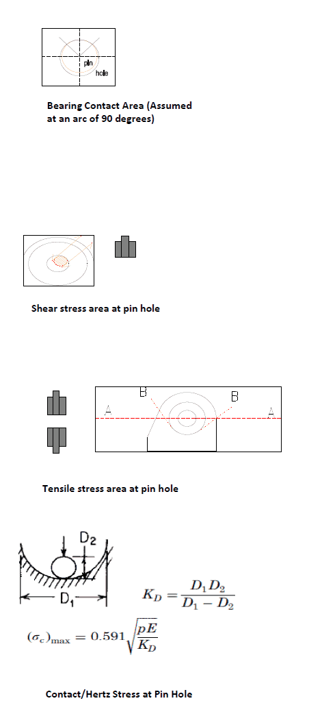
Various stresses on padeye hole
- The Main Plate – the main plate of the pad-eye is subjected to the load which is transferred to the base of the plate where it is welded to the deck of the vessel. There are three types of stresses which the main plate is subject to:
- Tensile stress: tensile stress is caused by the component of the force which is perpendicular to the horizontal section of the base plate, i.e., the vertical component. The bearing area is the area of the base, and stress is calculated from the vertical component divided by the base area.
- Bending Stresses: The force on the pad-eye, when resolved in the three directions, causes bending moments on the pad-eye as well. The component of the force along the horizontal (Y-axis) will make the main plate bend along its strong axis. The vertical force, if not passing exactly through the middle of the base, will add to the moment along the strong axis, while the lateral load will make the plate bend along the weak axis (Y-axis). The stress will be calculated by dividing the moment by the section modulus of its corresponding axis.
- Shear Stresses: Since the plate is loaded in both horizontal and lateral directions, shear stress is calculated in both directions. The shear area is the area of the base
- Von Mises Stress: The Von-Mises Stress is also calculated as a combined body stress on the pad-eye.
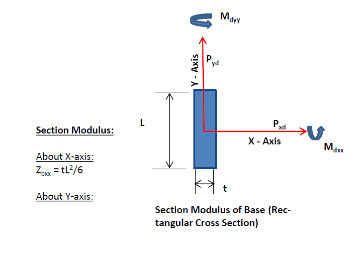
Bearing Area and Forces/Moments on Main Plate
- The Base Weld – the base weld of the pad-eye secures the pad-eye to the deck of the vessel. As such, the loads on the pad-eye are transferred to the base weld. Similar to the main plate of the pad-eye, the base weld is subject to the following:
- Tensile stress – the tensile stress on the weld results from the vertical component of the force. The weld bearing area is calculated by multiplying weld throat size with weld length. The stress is calculated by dividing the vertical component of the force by the bearing area.
- Shear Stress – The weld is also subject to shear stresses due to the horizontal and lateral components of the pad-eye load. The bearing area is same as for tensile stress.
- Bending Stresses: similar to the main plate, the weld at base is subject to moments due to the three components of the forces. The moments are about the horizontal and lateral axes. These moments cause bending stresses which can be calculated by dividing the moment by the section modulus of the weld in the respective direction.
- The cheek weld: The cheek plate is welded to the main plate with a circular weld. The load on the pad-eye can be considered to apply on the cheek weld in proportion to its thickness compared to the pad-eye’s thickness (2 x cheek plate thickness + main plate thickness). The weld area is the throat size x curcumference of the cheek weld. The stress is calculated by dividing the proportional load by the weld area.
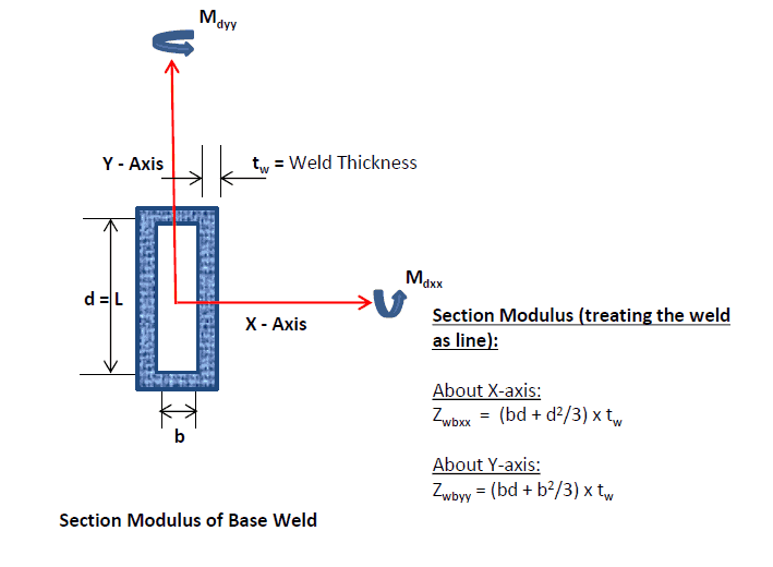
Bearing area and forces/moments on base weld
In some cases of pad-eyes being used for heavy duty applications like heavy-lift or transport of heavy cargo, a simple check may not suffice and a full fledged FE Analysis in a tool like ANSYS may be needed.
That brings us to the end of this article. While pad-eyes may look small, their design involves multiple checks and intricacies which come into play depending on the geometry and usage of the pad-eye. Whether designing a new pad-eye from scratch or evaluating an existing pad-eye for suitability to a particular operation, these factors need to be considered carefully for a successful operation.
Looking for help with designing or selecting the right pad-eye for your operation? Do take a moment to take a look at our pad-eye calculators (below) which greatly help reduce your time for design.
-
Bollard Pull Calculations for Barge
$49.00 Add To Cart -
Bollard Pull Calculations for Ships
$79.00 Add To Cart -

Cargo Forces & Accelerations – Open Ocean
$49.00 Add To Cart -
Pipe Stacking Height Calculator (Bare Steel Pipes)
$39.00 Add To Cart -
Pad-Eye Design Spreadsheet
$49.00 Add To Cart -
Stopper Design Spreadsheet
$49.00 Add To Cart -
Bollard Strength Check Spreadsheet
$39.00 Add To Cart -
Ship Squat Calculator
$49.00 Add To Cart -

Towing Bridle Design Spreadsheet
$39.00 Add To Cart -
Stanchion Design Spreadsheet
$49.00 Add To Cart -

Towing Bridle Force Calculator
$29.00 Add To Cart -
Lashing Design (4 Point Lashing, IMO CSS)
$49.00 Add To Cart

Please let me see.