In Part 1 of this article, we saw a step by step guide to calculate the Environmental forces on a vessel based on “Standard” environmental criteria defined in Section 3 of OCIMF Mooring Equipment Guidelines Fourth Edition (MEG-4) in order to determine the ship’s design MBL which in turn can be used to size the various components of the vessel’s mooring system, like bollards, fairleads and winches. Various parameters like loading conditions, tidal variations, WD/T ratio etc. were discussed and calculation of wind and current forces on the vessel based on coefficients was presented.
In Part 2 of the article we will look into how to
- Select a generic mooring line layout
- Calculate static Equilibrium of the vessel and stiffness of mooring line layout
- Determine Ship design MBL
Mooring Pattern
The vessel mooring pattern is to be designed to effectively counter the environmental forces from any direction. This means that the lines should be able to cope horizontal as well as transverse loads. The mooring pattern should therefore have lines along longitudinal direction to prevent motion in forward and aft directions and also in the transverse direction to prevent motion away from the berth. The longitudinal lines are knows as spring lines and the transverse lines are known as breast lines. The pattern also depends on the provisions at the terminal and it should be chosen, as much as possible, to keep the spring lines parallel and breast lines perpendicular to the ship length.
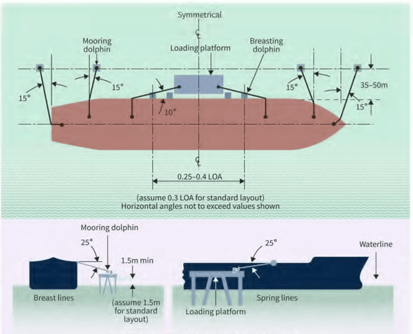
Mooring Pattern (Source: OCIMF MEG-4)
MEG4 provides the below guidelines for a generic mooring line layout.
- Breast mooring lines should be at an angle less than 15o to the perpendicular axis of the ship.
- Spring mooring lines should be at an angle less than 10o to the side of the ship.
- Maximum vertical angles of 25 degrees should be assumed for the lightest ballasted condition.
Static Equilibrium
A vessel subject to environmental forces/moments will move in the forward or transverse directions or rotate about the vertical axis i.e. the vessel will have surge, sway or yaw respectively. The vessel motion will change the relative distance of the fairlead from the shore anchor point, changing the length of the mooring lines. The lines, generally speaking, behave like a spring and the force exerted is proportional to the change in length of the line. This characteristic of the lines can be found from the data sheet of the line from the manufacturer. The change in length of the lines increases the tensions in the lines and the combined load exerted by all the lines then balances the total environmental loading. This condition of the vessel where the environmental loading is balanced by the mooring lines is known as static equilibrium.
Ship design MBL calculation
A simple spring formulation can be applied to evaluate the translations/rotations of the vessel in static equilibrium under the effect of the calculated environmental loads. Once a mooring system for the vessel at the berth has been chosen, for given position of the vessel the change in length of each mooring line with respect to its initial (un-stretched) length can be calculated using a simple spring formulation F = k δL where F is the line tension, k is the stiffness of the line and δL is the change in line length. Tension in each line can be aggregated to get the net loading on the vessel.
Hence we can calculate the translation/rotation of the vessel that will result in unit force/moment on the vessel by the mooring lines. Let’s call this the inverse stiffness k’. If k’ is displacement produced by unit force on the vessel, the total displacement X produced by the net environmental loading F can be calculated as X = F k’. The new position for the ship can be used to re-calculate the net mooring loads on the vessel and compared to the environmental forces and the whole process can be repeated until static equilibrium is achieved. The total length of the mooring line from winch to bollard should be used in the calculations. Also the stiffness of the lines change with use and the calculations should use the stiffness of used lines instead of new lines. The above can be summarized in below steps,
- Calculate total environmental forces/moments on the vessel in surge, sway and yaw directions. E.g. Fx is the net environmental force in the surge direction
- Determine the inverse stiffness of the mooring system in terms of amount of surge/sway/yaw per unit force/moment. E.g. k’ m/N is the stiffness of the vessel in surge direction.
- Calculate the total amount of surge/sway/yaw. E.g. Surge (m)= Fx * k’
- Calculate the resultant mooring forces based on the new position. E.g. Rx is the net mooring force in the surge direction.
- Compare the environmental forces and resultant mooring forces i.e. Fx = Rx?
- Several iterations of steps 2-5 may be required until static equilibrium is achieved.
Once static equilibrium is achieved, maximum mooring restraint force can be determined and used in the flowchart below, provided by MEG4, to calculate the ship design Minimum Breaking Load i.e. Ship design MBL. With the vessel in static equilibrium, the tensions in each mooring line can be determined. Since there are several components in the mooring pattern that support multiple mooring lines, the total loading on such component can be used to calculate the Ship design MBL as

The ship design MBL is the MBL of a new, dry mooring line for which a ships mooring system is designed and that meets the mooring restraint requirements as defined in MEG4, section 3. All other components of a ship’s mooring system are based on this ship design MBL, with defined tolerances.
It must be noted that static analysis may only be suitable for benign environment as we are assuming the lines as simple springs. In other cases dynamic analysis for the vessel motions and line tensions should be performed.
The steps above are also lined out in OCIF MEG-4, and shown in the figure below.

Ship’s Design MBL Calculation Steps (Source: OCIMF MEG-4)
In Part 3, we will further look into using this Ship design MBL for line selection and to determine D/d ratio (bend dia/rope dia) of mooring line and other parameters.
Do check out some products relevant to OCIMF MEG-4 below. The product for calculation of Ship’s Design MBL is in progress and shall be out soon!
Disclaimer: This post is not meant to be an authoritative writing on the topic presented. TheNavalArch bears no responsibility for the accuracy of this article, or for any incidents/losses arising due to the use of the information in this article in any operation. It is recommended to seek professional advice before executing any activity which draws on information mentioned in this post. All the figures, drawings and pictures are property of thenavalarch except where indicated, and may not be copied or distributed without permission.
-
Mooring Forces Calculator (Stern on Quay, 4-Point Mooring)
$99.00 Add To Cart -
Mooring Forces Calculator (Port or Stbd on Quay)
$99.00 Add To Cart -

OCIMF Environment Forces Calculator – Tankers (Updated toMEG-4)
$99.00 Add To Cart -

OCIMF Environment Forces Calculator – Gas Carrier (updated to MEG4)
$99.00 Add To Cart -
Capstan Design (Required power for Berthing)
$49.00 Add To Cart -
Mooring Line Catenary App
$99.00 Add To Cart -
Motion Response Calculator
$99.00 Add To Cart -
OCIMF Anchoring Environment Loads Calculator
$99.00 Add To Cart -
Fishing Vessel Equipment Number Calculator
$39.00 Add To Cart -

Mooring Line Catenary with Buoy
$99.00 Add To Cart -
Sale!
OCIMF Berth Mooring Design Calculator
Original price was: $299.00.$249.00Current price is: $249.00. Add To Cart -
Ship Design MBL Calculator – IACS
$99.00 Add To Cart

Good day,
In ref to the product for calculation of Ship’s Design MBL, would you kindly advise when expected to be released?
Hi Alex
Thanks for your query. At the moment the app is under development, and we may not be able to give a specific launch date. We’re looking to launch it before the end of the year
Such a useful article! Well done! One question if I may, after calculating the individual line restraints, I am not sure if rope or wire should be used for Ship Design MBL calculation as they give slightly different results due to WLL.
Hi Jackson
Thanks for your feedback.
Generally, since MBL is a design parameter that should be based on the most conservative case, we recommend that you use the material that gives more conservative results.
have the product for calculation of Ship’s Design MBL been released ?
My ship is 24000 tons , how to measure the strength of mooring rope??
Hi Essam
Strength of mooring rope is a function of the EN of the vessel. Please refer to our articles on Equipment Numeral. If you need further help, pelase write to info@thenavalarch.com. Thanks
My ship is 43,310 grt how much is mbl
Hi Darold
We’ll need more info on that. Can you please send us an email with details to info@thenavalarch.com?
Hi, Sir,
For the vessels which built before2024 and after 2007, if we know the value of SWL, how to get the SDMBL? Thanks!