Introduction
Fillet welds are the most commonly used weld types in marine structures. A fillet weld is used when there are two pieces of metal that are joined perpendicular to each other or at an angle. In this article, we will explore how to select the right size fillet weld for the case when the pieces of metals are to be welded perpendicular to each other in a tee-joint. The article follows the requirements of Eurocode 3: Design of steel structure (EN 1993 Part 1)
Weld Geometry
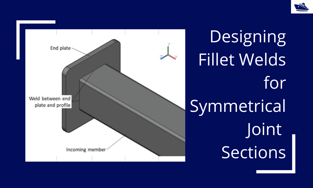
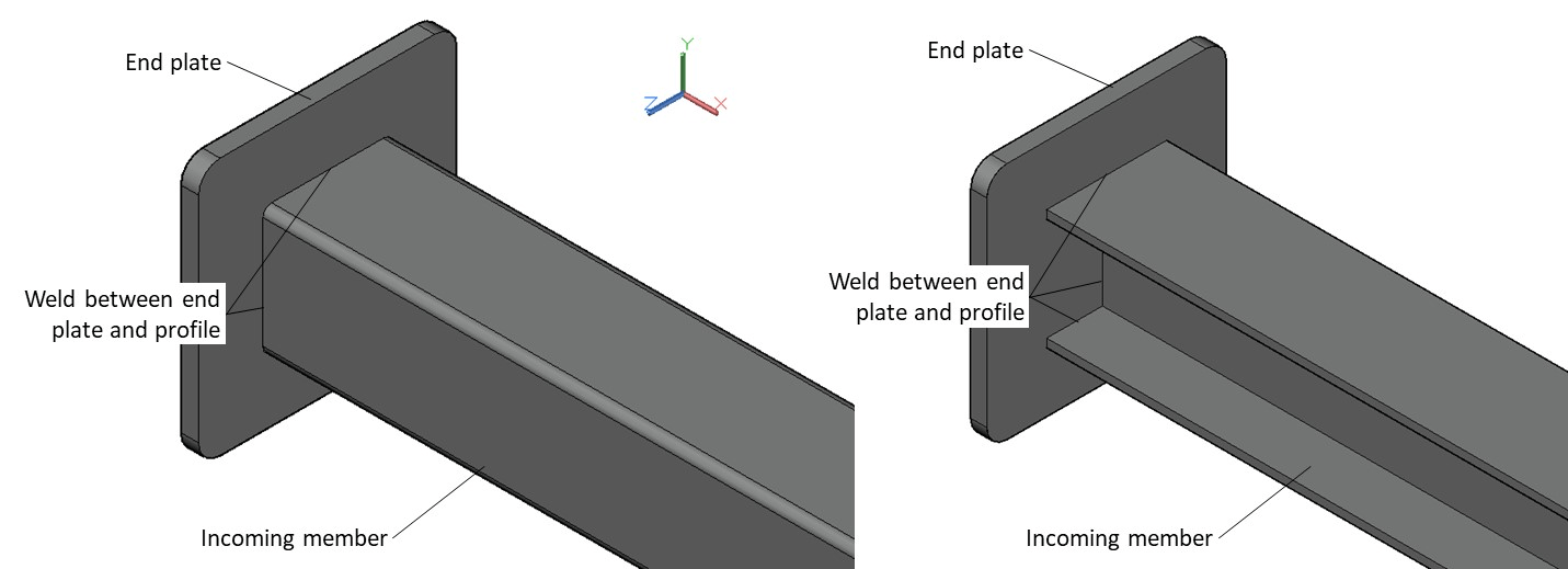
The fillet weld explored in this article is one that is between an incoming member and an endplate. This is shown in the figure below. The incoming member can have a different section shape: it can be an I-section or an RHS section (Rectangular Hollow Steel) or some other section. The method described in this article is only applicable to double symmetrical sections.
Material Properties
The material properties that are relevant will be the properties of the plate, and of the weld.
For the plate, the Yield Strength, Tensile Strength, and the material factor. The material factor γ is a safety factor that is applied based on EN 1993-1-1
For the weld, the Ultimate Strength is used for strength checks, together with a material factor γ and a correlation factor β that are applied based on EN 1993-1-1 and Table 4.1 of EN 1993-1-8 respectively.
Forces
Next, we take a look at the forces on the weld. Any structure will be subject to 6 degrees of freedom, each designated by a force/moment. The weld is subject to the following:
- Axial force
- Shear force, Y-direction
- Shear force, Z-direction
- Moment about X-axis
- Moment about Y-axis
- Moment about Z-axis
Weld Properties
The section properties of the weld need to be computed for the stress checks to be done. These include the bearing area, shear areas, the moment of inertia about the two axes, and the section moduli about the two axes. Depending on whether the section is an RHS section or an I-section, the formulae for these properties will vary.
Stress Checks
Once the section properties are calculated and the forces on the weld are available, we need to perform the stress checks on the weld.
There are different types of stresses that need to be checked:
- Stress due to Axial Force – the axial force (Fx) leads to two types of stresses – one is the normal stress which is calculated by dividing the axial force by the axial cross-sectional area of the weld. The other stress due to the axial force is the shear stress which is also the same as the
- Stress due to Shear Force – the forces in the other two directions, if Fy and Fz lead to shear forces on the weld. The shear force is calculated by dividing the shear force by its respective shear area, i.e.,
Shear Stress due to Fy = Fy/(Shear area in the y-direction)
Shear Stress due to Fz = Fz/(Shear area in the z-direction)
- Stress due to Moments – the three moments along the three axes each produce a different type of stress on the weld, and these can be summarized as below:
- The moment about the Y-axis produces normal stress as well as shear stress that can be calculated by dividing the Moment by the relevant section modulus about the Y-axis
- The moment about the Z-axis produces a normal as well as shear stress that can be calculated by dividing the Moment by the relevant section modulus about the Z-axis
- The moment about the X-axis (axial moment) produces torsional shear stress that can be calculated from the formula
Torsional Shear Stress = Axial moment x extreme axial distance/polar moment of inertia
The axial distance and the polar moment of inertia depend on the type of section selected, and can be calculated using standard formulae for the I-section or RHS section
Final Stresses on the Throat Section
The final stresses on the throat section of the weld can be summarized as below:
- Normal stress perpendicular to the throat σ⊥ – this is a sum of the individual normal stresses due to the axial force Fx, and normal stresses arising from the moments My and Mz
- Shear stress perpendicular to the axis of the weld τ⊥ – this is the sum of the shear stress due to the axial force Fx, and the shear stresses due to My and Mz
- Shear Stress Parallel to the axis of the weld τǁ – this is the sum of the shear stress due to Fy, shear stress due to Fz and the torsional shear stress due to Mx
Acceptance Criteria
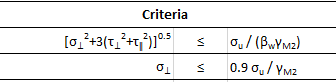
The criteria check against allowable stresses are provided below. These need to be met for the weld to be acceptable
- Combined Stress check: the combined stress [σ⊥2+3(τ⊥2+τǁ2)]5 must be less than the allowable combined stress. Allowable combined stress = Ultimate Weld Strength/(Material Factor for weld x correlation factor for weld)
- Normal Stress Check: the normal stress should be less than the allowable normal stress. Allowable normal stress = 0.9 x Ultimate Weld Strength/Material Factor for weld
References
- Eurocode 3: Design of steel structure; Part 1-8: Design of joints
- Eurocode 3: Design of steel structure; Part 1-1: General rules and rules for buildings
- https://en.wikipedia.org/wiki/Fillet_weld
That brings us to the end of this article. Please do check out TheNavalArch’s product on weld design for fillet welds.
Disclaimer: This post is not meant to be authoritative writing on the topic presented. thenavalarch bears no responsibility for the accuracy of this article, or for any incidents/losses arising due to the use of the information in this article in any operation. It is recommended to seek professional advice before executing any activity which draws on information mentioned in this post. All the figures, drawings, and pictures are property of thenavalarch except where indicated, and may not be copied or distributed without permission.
https://thenavalarch.com/software/maritime-industry-thenavalarch/ship-design/ship-strength/weld-check-spreadsheet-joint-sections/
A quick empirical method for resistance estimation of planing vessels
Resistance estimation for a vessel is a fundamental exercise in design of the vessel. Resistance is a property that depends on the vessel’s shape and form. A conventional ship-shaped vessel with a bulb will have completely different resistance characteristics compared...
Powering the maritime industry with Hydrogen – Part 2
Powering the shipping industry with hydrogen - Part 2: Hydrogen propulsion on a ship - opportunities and challenges Introduction In the Part 1 of this article, we explored the basic properties of Hydrogen as a fuel, and also the opportunities and challenges...
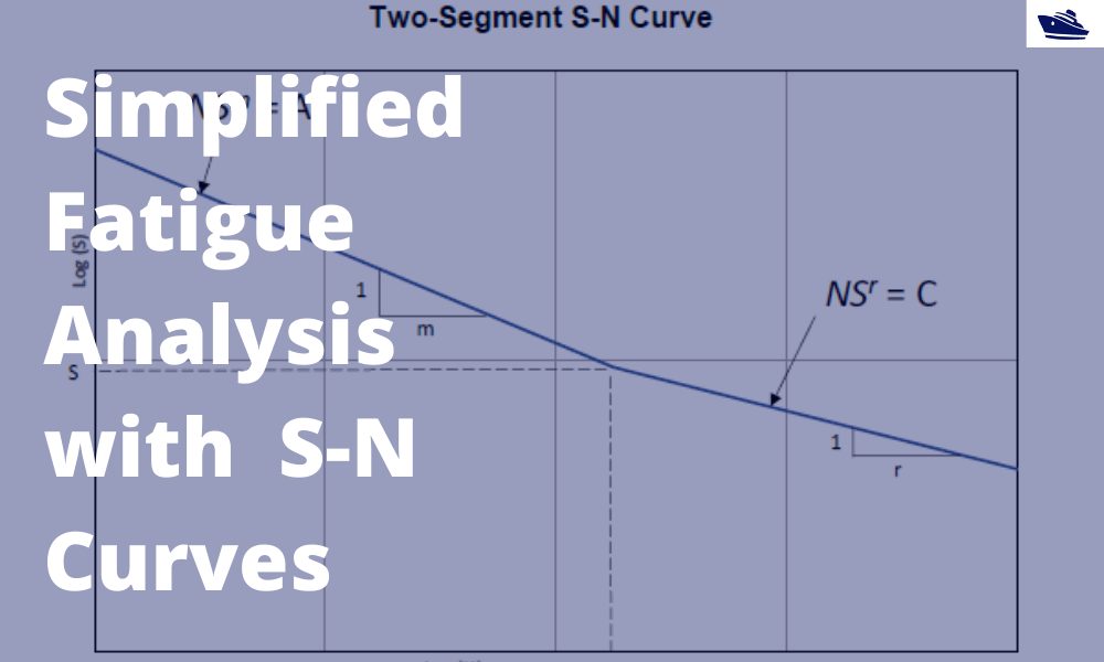
A simplified method of performing fatigue analysis of offshore structures
A simplified method of performing fatigue analysis of offshore structures Introduction An offshore structure is subject to environmental loads of waves, wind and current. By their nature, the resulting wave loads on the structure are cyclical. These cyclical...

Powering the shipping industry with hydrogen: opportunities and challenges (Part 1)
Part 1: About Hydrogen – Basics, Opportunities, and Challenges Of late, hydrogen has been generating quite a buzz in the energy sector with its possibility as a clean source of energy. The shipping sector is not untouched, and this article explores the possibilities...
The importance of analysis in nearshore pull-in operation in offshore wind farms
Introduction Over the last 10 years, the global wind energy business has increased manifold. In the next 5 years, the rate of installation is expected to accelerate. This is mostly driven by the opening up of Chinese and US markets. A primary chunk of this market is...
Vessel Draft Survey Accuracy
by Chris Zeringue, Owner, MTS Marine Techincal Surveyors The key to accuracy in a Vessel Draft Survey may very well be found in a hole in the ship. I boarded my...

How to use a ship’s hydrostatics to calculate its draft and trim
Introduction A ship’s hydrostatics, or hydrostats, is an oft used term in maritime parlance, and it refers to the characteristics when it is floating. What characteristics are these? How are these determined, and how can we read and understand them? Understanding...
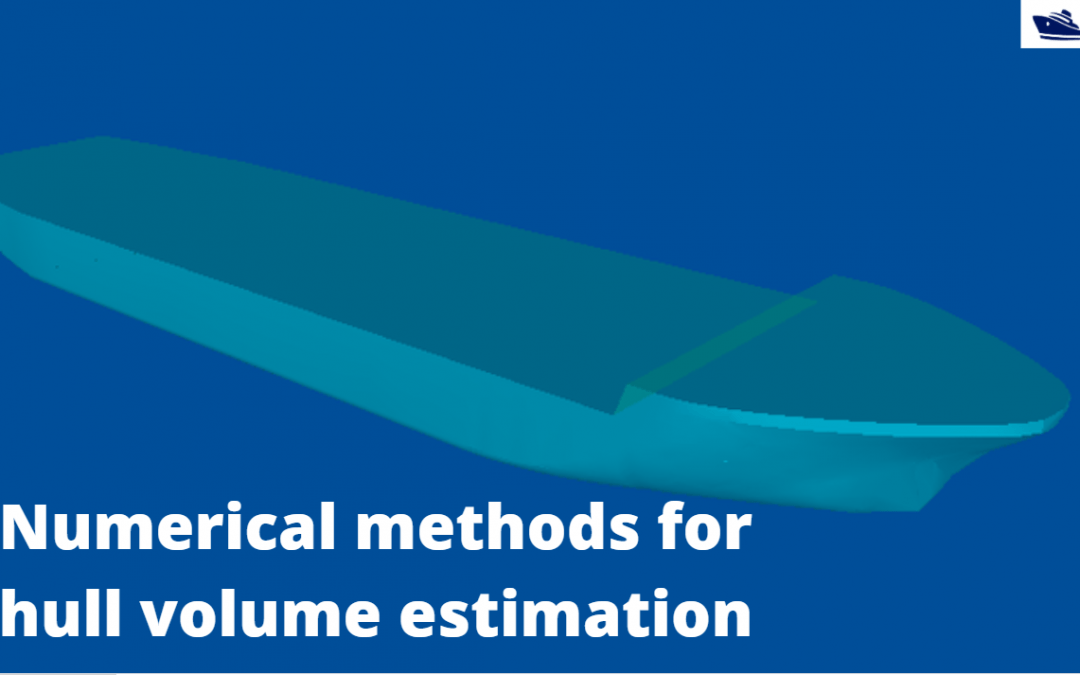
Numerical integration methods for hull volume estimation
Introduction The hull of a ship is a complex 3D geometry, and finding out its simple properties like volume, centroid, etc. is not possible through simple formulae unlike standard shapes like cuboid or a cylinder. How do we find a property, say the volume of a...
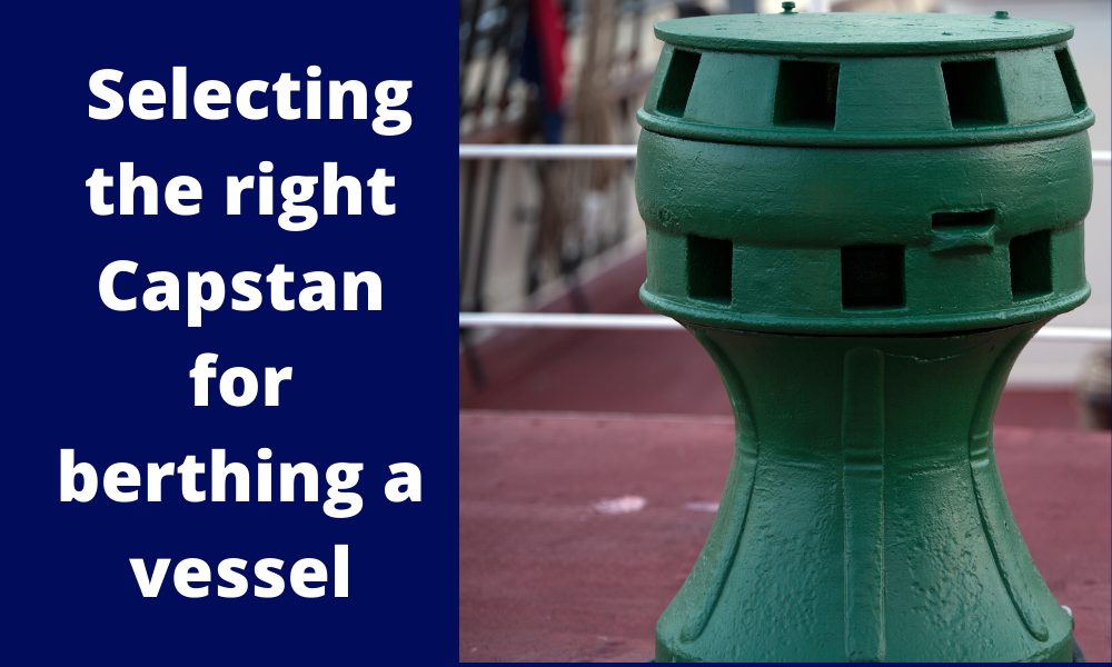
Selecting the right Capstan for berthing a vessel
Introduction Capstans are frequently deployed mooring equipment used on all types of vessels. Capstans are berthing/mooring equipment used to multiply the pulling force on mooring ropes. Traditionally, Capstans were operated manually but in modern ships, they are...
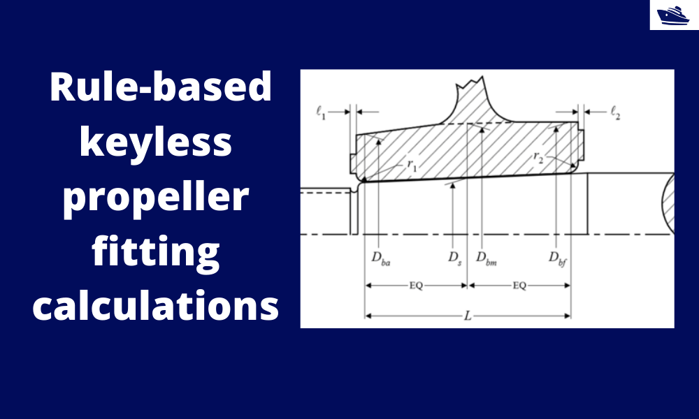
How to do rule-based fitting calculations of a keyless propeller
Introduction A keyless propeller, as the name implies, requires no key for fastening the propeller on the cone of the propeller shaft. How is the torque then transferred to the propeller? The torque is transferred by the friction between the propeller and the...

Hey