
Introduction
GRP laminates are widely used in the fabrication of high-speed crafts and light crafts/boats globally. GRP stands for Glass Reinforced Plastic. As the name suggests, GRP contains glass fibers embedded into a plastic resin. This gives it higher strength, durability, and also a smooth finish [Ref 3].
A laminate used for the fabrication of boats will usually have multiple layers of reinforcements of GRP to achieve the desired strength. In this article, we will learn about a method to calculate the desired number of layers of laminate reinforcements to be used to attain a desired thickness of the laminate. The article follows the formulations provided in the Indian Register of Shipping, Rules and Regulations for the Construction and Classification of High-Speed Crafts and Light Crafts Chapter 7 General Hull Requirements for Fiber Composite and Sandwich Constructions, Section 5 Material Properties and Testing.
CSM vs Woven Roving
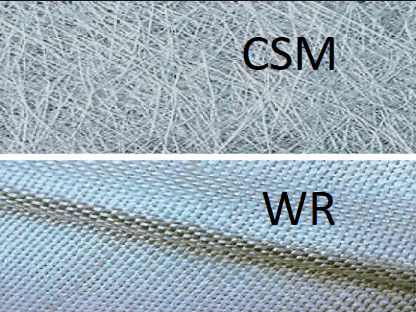
There are two major types of GRPs used in boat fabrication. The first one is CSM, short for Chopped Strand Mat. The CSM has random fiberglass of various lengths dispersed through the resin to provide equal distribution in all directions. Woven Roving, on the other hand, resembles a cloth with woven strands of fibers to form a lattice pattern (see fig below)
CSM vs Woven Roving
Application to FRP boats
FRP, or Fiber Reinforced Plastic boats are made from laminates which have multiple layers of either Woven Roving (WR) or Chopped Strand Mat (CSM), or a combination of the two. The resulting laminate must have the requisite strength and other material properties suitable for its purpose.
How thick the laminate should be? The minimum thickness is provided in the rules of Classification Society to which the boat is classed. Since the laminate is made of multiple layers of reinforcements of CSM or WR, it is important to be able to select the right number of layers of CSM or WR to be able to attain the requisite thickness of the laminate.
Hence, if
- nCSM is the number of layers of CSM with the thickness of each CSM layer being tCSM, and
- nWR is the number of layers of WR with the thickness of each WR layer being tWR, and
- tREQ is the required thickness of the laminate, then
tREQ = nCSM x tCSM + nWR x tWR
Properties of WR and CSM
Since glass is an integral part of the reinforcement layer, the properties like the strength of the laminate are expected to be dependent on the amount of glass reinforcement in the laminate layer.
WR and CSM differ in their mechanical properties owing to the difference in their structure. The tables below demonstrate the difference in their properties
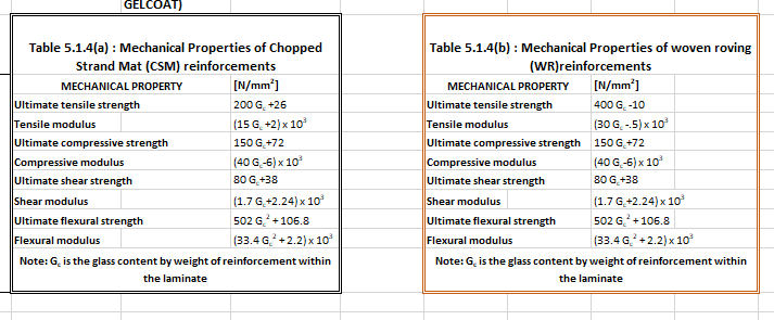
We can note from the tables above that the property GC is central to calculating all the properties of the laminate layer. GC is the Glass Content Ratio by weight of reinforcement within the laminate. Thus the calculation of GC is a pre-requisite to the calculation of the laminate layer’s properties.
Thickness calculation for the laminate
Now we come to the next stage – how to calculate the number of WR or CSM layers needed to achieve a desired thickness?
For this, we will refer to a formula from the Indian Register of Shipping rules [Ref 1]. The formula calculates the thickness of the ith laminate layer from two properties:
- Weight of reinforcement of the layer (expressed in g/m2), Wi
- The Glass Content Ratio, GC, explained above
The formula is shown below:
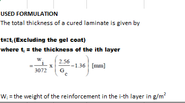
We can see that the total thickness is the sum of the thicknesses of individual layers. The thickness of the ith layer is given by
ti = wi/3072 x (2.56/GC – 1.36), in mm
The layers of the laminate can be made up of WR or CSM or a combination of both. We can achieve a target thickness by trying out different types and numbers of CSM and WR layers, calculating their individual thicknesses and adding them up to check if the minimum thickness (as prescribed by Class rules) is being achieved.
The material properties of each layer can also be calculated using the value of GC for the layer. The material properties of the entire laminate then can be calculated as a thickness-averaged value for all layers.
For example, the ultimate tensile strength (SU) can be calculated thus:
SU = Σ (Sui x ti)/Σ(ti)
Looking at the above calculations, a spreadsheet solution can be set up for performing the calculations in the following steps:
- Step 1 – calculate the required thickness of the laminate from Class Rules
- Step 2 – add multiple rows in a spreadsheet, each row representing a laminate layer which can be either a WR or CSM.
- Step 3 – keep adding rows of laminate layers and calculate their individual properties (thickness and other properties), at the same time calculating the cumulative properties of the laminate.
- Step 4 – The required number of layers is obtained when the target thickness of the laminate is reached
From the steps above, an optimum number of laminate layers required can be obtained. Ending up with a thinner laminate means weaker laminate and thicker laminate means excess material is being spent, and this method can provide the optimum.
TheNavalArch has developed its own app that can be used to calculate the optimum number of layers required for a laminate of requisite thickness. Please do spend some time to check it out
References
- INDIAN REGISTER OF SHIPPING – Rules and Regulations for the Construction and Classification of High Speed Crafts and Light Crafts, Chapter 7 General Hull Requirements for Fibre Composite and Sandwich Constructions, Section 5 Material Properties and Testing
Disclaimer: This post is not meant to be authoritative writing on the topic presented. thenavalarch bears no responsibility for the accuracy of this article, or for any incidents/losses arising due to the use of the information in this article in any operation. It is recommended to seek professional advice before executing any activity which draws on information mentioned in this post. All the figures, drawings, and pictures are property of thenavalarch except where indicated, and may not be copied or distributed without permission.

Why the bollard pull calculation method for a barge won’t work for a ship
In my working with the marine transportation industry for more than a decade now, I have come across many different calculations for required bollard pull for both barges and ships. The principles of the calculation are same, whether it is a ship, a barge...
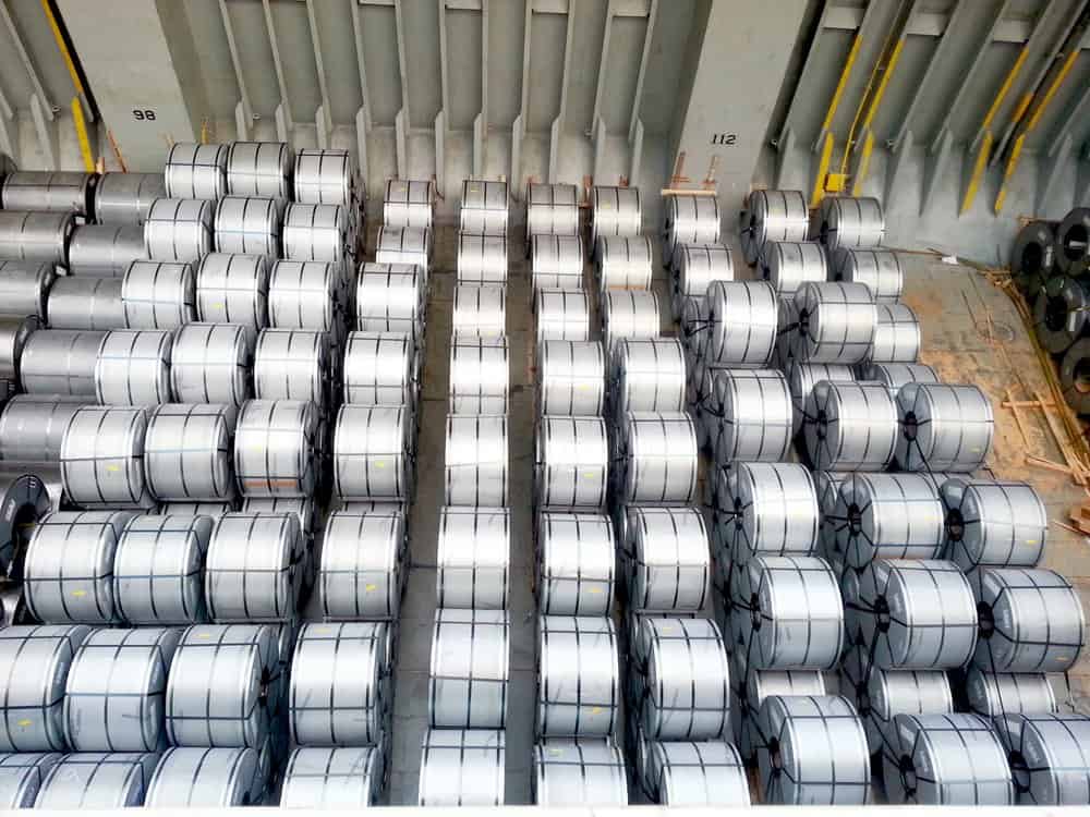
STEEL COILS LOADING – ITS CHALLENGES AND WAYS TO OVERCOME
STEEL COILS LOADING – ITS CHALLENGES AND WAYS TO OVERCOME by Mr. Spiros Malliaroudakis (Founder & Managing Director, S.A. Malliaroudakis Maritime (UK) Ltd) The loads derived from steel coils loading are very concentrated, leading to higher stresses...

Naval architecture, new challenges and a new horizon
Naval architecture, new challenges and a new horizon by Lim Soon Heng, BE, PE, FSSS, FIMarEST Founder President, Society of FLOATING SOLUTIONS (Singapore) Civilization has arrived at a point of inflexion triggered by global warming and rising sea levels....
Mooring System Design and Analysis
Mooring System Design and Analysis by Rahul Kanotra, Consultant Naval Architect As the offshore industry moves towards greater technological advancements, one thing that has plagued the engineers is the “plug and play” computer programs or software. I am not against...
Cargo Stoppers – why they are critical and how to design them
Stoppers and their critical role in seafastening of cargo Introduction A cargo transported on the deck of a ship is subject to many forces. These forces comprise of the inertial forces due to the ship motions – the three translations and three rotations – and the...

Are you chartering a tug bigger than necessary for your Barge?
Barges are one of the most frequently used means for transporting deck cargo of different shape, size and weight. While some barges are self-propelled, the majority is towed by another vessel called a ‘Tug’. Once an owner or charterer...
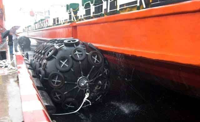
Fendering – an Introduction
In this two part article we will talk about Fendering, which is one of the basic but critical operations related to a ship. Fendering is, basically, protecting the ship’s sides from contact with another body (which can be another ship, jetty or quay wall). It can also...

Loadouts – An introduction
Image source: Flickr Loadout Operations - an Introduction Loadout is a term oft heard of in the marine/offshore industry parlance. Loadout is generally referred to the operation of transferring a Cargo or a Structure from the place of fabrication to a sea-borne...
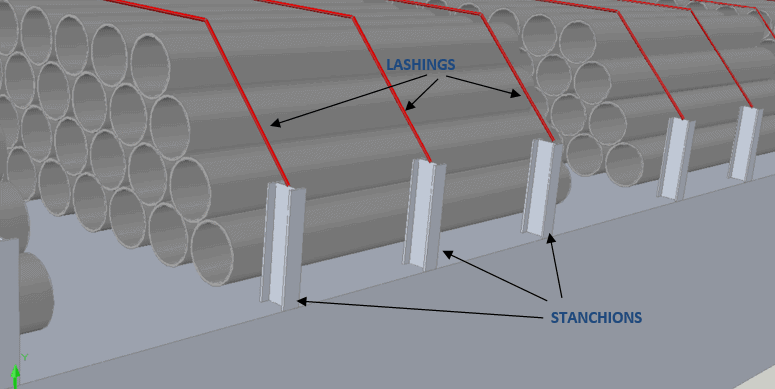
Introduction to Pipe Transportation – Part 3 (Engineering)
Introduction to Pipe Transportation - EngineeringIn Part 1 we learnt about pipes, while in Part 2 we learnt about Planning and Scheduling of pipe transport operations. In this part, we will learn about Engineering.Phase 3 – Engineering.Engineering for pipe...
Introduction to Pipe Transportation – Part 2 (Planning & Scheduling)
In Part 1, we looked at the properties of pipes. In this section, we will be looking at the Planning & Scheduling of a pipe transportation operation (see below, Phase 1 & 2) SECTION 2: PLANNING, SCHEDULING, AND ENGINEERING FOR A PIPE TRANSPORT PROJECT Source:...

Thanks