Introduction
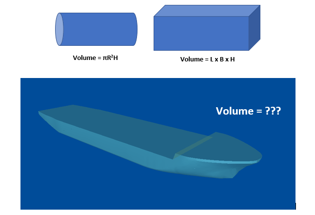
The hull of a ship is a complex 3D geometry, and finding out its simple properties like volume, centroid, etc. is not possible through simple formulae unlike standard shapes like cuboid or a cylinder.
How do we find a property, say the volume of a complex shape like the hull? We’ll take a detailed look at this article.
The approach
The approach for complex geometries is called ‘integration’, which means dividing the geometry into several numbers of smaller sized pieces, calculating the volume of each piece, and adding them up together (integration) to give the volume of the entire geometry.
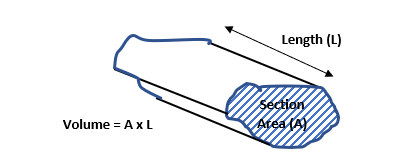
Mathematically speaking, the volume of a body with a fixed section shape is given by Volume = Section Area x Depth (see figure below).
However, the section of a hull keeps changing along its length. How do we use the above formula, then?
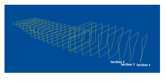
If we can divide the entire body of the ship into several number of sections along its length, then each section becomes a 3D shape in itself, with each section approximately making a trapezoid having different section areas at its ends. This approach is illustrated below.
The trapezoidal rule
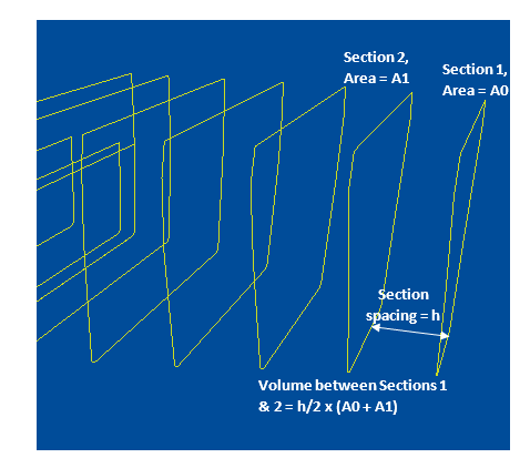
The simplest form of integration is the trapezoidal rule. In this rule, we simply divide the length of the vessel into a number of equally spaced sections, with each section resembling a trapezoid. We can see that this approximation of a section as a trapezoid is feasible only when the section length is small, i.e., we have to divide the length into many sections (usually more than 10) to be able to use the trapezoid approximation.
If we divide the length into 10 equally sized sections, then the length of each section is h = L/10, where L is the length of the ship.
Let’s take the first section. If the area of its aft end is A0 and the area of its fwd end is A1, with the length being h, then the volume of the section is given by:
V1 = ½ x h x (A0 + A1)
Similarly, the volume of the second section will be
V2 = ½ x h x (A1 + A2), where A2 is the section area of the fwd end of section 2
V3 = ½ x h x (A2 + A3), where A3 is the section area of the fwd end of section 3
and so on.
The final result of the volume of the hull will be
V = V1 + V2 + …. + V10
- V = ½ x h x (A0 + 2 x A1 + 2 x A2 + 2 x A3 + ….. + 2 x A9 + A10)
The above formula is called the Trapezoidal rule of integration to get the volume of the hull. We can see that the formula will give accurate results if the number of sections is high. However, if there’s a rapid change is the section area between two ends of a section, then this method leads to greater inaccuracy, as it assumes the variation between the two ends to be linear which may not be the case always as the ship is a curved body.
Simpson’s Rules
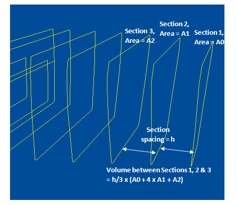
For cases where the change in section area is more rapid (say, for the complicated fwd and aft ends of the vessel), we need a more accurate estimation. The Trapezoidal rule is based on a linear approximation by using a section with two ends as the unit of calculation. What if we take a unit with three sections as the unit of calculation? This is demonstrated below:
This method is called Simpson’s first rule, and it considers the variation between the three sections to be approximated by a curve of the third order.
From Simpson’s first rule, the volume of the first unit is given by
V1 = h/3 x (A0 + 4 x A1 + A2)
The volume of the second unit onwards will be given by
V2 = h/3 x (A2 + 4 x A3 + A4)
V3 = h/3 x (A4 + 4 x A5 + A6)
and so on.
Thus, we note the following about Simpson’s first rule:
- The total number of sections has to be odd (3,5,7 etc.)
- The formula for several sections will be
V = h/3 x (A0 + 4 x A1 + 2 x A2 + 4 x A3 + 2 x A4 + 4 x A5 + …. + An)
We notice that every odd-numbered section has a multiplier of 4, while every even-numbered section has a multiplier of 2. The two end sections have no multipliers
If we can tabulate the section areas and their respective multipliers, then the calculation can be done in a simple template as shown below:
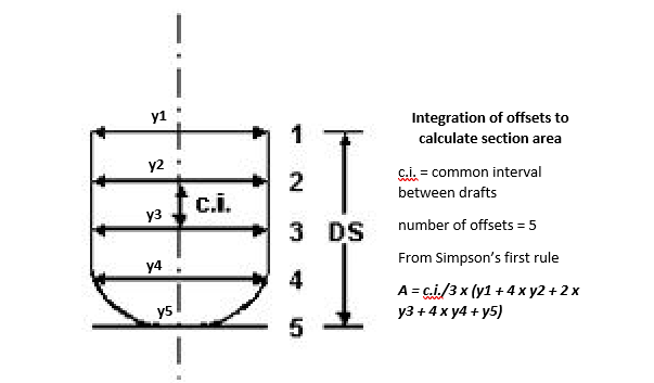
What if we want to calculate the individual section areas too using numerical methods? The same process applies – divide the section using equally spaced offsets along with the depth of the section (odd-numbered for Simpson’s first rule), and use the correct multipliers to get the section areas. Once the section areas are obtained for equally spaced stations along the length of the vessel, then the numerical integration can be applied again to provide the volume of the hull as well.
Thus,
- Numerical integration of offsets along the depth of a section gives Section Area
- Numerical integration of Section Areas along the length of the vessel gives Hull Volume
If we take a unit with four equally spaced sections as the unit for calculation of the volume, then the resulting formula is called Simpson’s Second Rule which is given by:
V1 = 3h/8 x (A0 + 3 x A1 + 3 x A2 + A3)
V2 = 3h/8 x (A3 + 3 x A4 + 3 x A5 + A6)
Extending this to several coordinates,
V = 3h/8 x (A0 + 3 x A1 + 3 x A2 + 2 x A3 + 3 x A4 + 3 x A5 + 2 x A6 …. + An)
This method is suitable only when the number of ordinates is 4, 7, 10, 13 etc.
One limitation of the ods presented above is that the section spacing has to be the same for all sections. There are methods like Tchebycheff’s rule that works for unevenly spaced sections, and that will be covered in future articles.
That brings us to the end of this article on calculating hull volume using numerical methods. Please do check out our related product that helps the user calculate the hull volume in a user-friendly format.
References
- Basic Ship Theory, K.J.Rawson, E.C. Tupper, Fifth Ed. 2001
- Transport Publication 13430 E, Department of Transport, Canada
Disclaimer:
Disclaimer:
This post is not meant to be an authoritative writing on the topic presented. thenavalarch bears no responsibility for the accuracy of this article, or for any incidents/losses arising due to the use of the information in this article in any operation. It is recommended to seek professional advice before executing any activity which draws on information mentioned in this post. All the figures, drawings and pictures are property of thenavalarch except where indicated, and may not be copied or distributed without permission. The views, information, or opinions expressed in the article are solely those of the author and do not necessarily represent those of TheNavalArch Pte Ltd and its employees
TheNavalArch Interview Series: Capt Robin Perera
TheNavalArch's Interview Series is an endeavor to get insights from the best engineering and...

Offshore Installation Vessels Stability Considerations
OFFSHORE INSTALLATION VESSELS STABILITY CONSIDERATIONS By Alan Crowle, BSc, MSc, MScbyRes, CEng,...
TheNavalArch Interview Series: Mr Victor Valera
TheNavalArch's Interview Series is an endeavor to get insights from the best engineering and...
TheNavalArch Interview Series: Mr Steven Lu
Mr. Steven LuManaging DirectorEpoch Offshore Engineering (Shanghai) Co., Ltd. TheNavalArch's...

TRANSPORT VESSELS FOR FLOATING WIND
By Alan Crowle, BSc, MSc, CEng, CMarEng, FRINA, FMAREST, FSCMS Masters by Researcher, University...
TheNavalArch Interview Series: Mr. Balakrishna Menon
Mr. Balakrishna MenonEngineering Director Mooreast (Asia) Pte Ltd ...

Floating Rice Fields, the quest for solutions to combat drought floods and rising sea levels
by Lim Soon Heng, BE, PE, FSSS, FIMarEST Founder President, Society of FLOATING SOLUTIONS...

CAPSIZE OF LIFTBOAT IN TRANSIT
This paper was originally presented in the 27th Offshore Symposium, February 22nd, 2022, Houston,...

FLOATING WIND TURBINES -TRANSPORTATION AND INSTALLATION ENGINEERING
By Alan Crowle, BSc, MSc, CEng, CMarEng, FRINA, FMAREST, FSCMS Masters by Researcher, University...
Preparation for Dry-docking of an oil tanker: A Chief Engineer’s approach
Introduction Dry-docking of a vessel is required at every 5 yearly intervals to carry out...


Nothn