The Philosophy
Cable hydrodynamic stability is one of the most fundamental design topics which are addressed by cable installation engineers. In its simplest form, a simple force balance approach may be considered to ensure that the cable is not displacing laterally when exposed to the maximum instantaneous hydrodynamic loads associated with extreme met-ocean conditions. If stability can be ensured in a cost-efficient way by applying a minimal amount of concrete weight coating only, this stability method when applied correctly can be regarded as a robust and straightforward approach.
The calculated lateral displacement will typically depend on:
– Cable weight and its hydrodynamic diameter,
– Wave induced water particle velocity
– Water current velocity
– Storm duration and
– Pipe-seabed interaction.
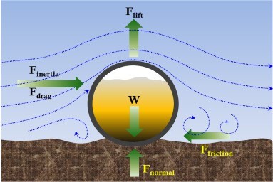
Figure 1: Force diagram of on-bottom stability on pipeline
The DNV Document DNVGL-RP-F109 “On-Bottom Stability of Submarine Pipelines” is currently the industry-accepted guideline to establish the design criteria. Note that although the dimensions applicable for the code suit the pipeline dimensions, the application has been extended to cables and flexibles. Various papers have shown that the application of pipeline guidelines on cable often leads to conservatism.
Limit state
A cable resting on the seabed will be exposed to hydrodynamic loads, both laterally and vertically, from wave – and current induced water particle velocity. If these loads exceed the resistance provided by the pipe seabed interaction, the cable will move.
A cable can be designed to allow for absolutely no lateral displacement and avoiding lift-off by fulfilling the following requirements:
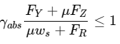
Equation 1: Horizontal stability unity check criteria
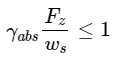
Equation 2: Vertical stability unity check criteria
where the following definitions apply:
FY: Time variable horizontal load acting on the cable under the design wave.
Fz: Time variable vertical load acting on the cable under the design wave.
µ: Coefficient of friction
ws: Cable submerged weight
Fr: Passive soil resistance
γabs: Safety factor for absolute stability
If a cable fulfills this requirement, analyses of the limit states in the following sections are not required. If a certain displacement is allowed, a maximum allowable displacement should be defined by the cable-owner and the design shall be based on dynamic analyses in the time domain during a design storm. The magnitude of the allowable displacement may be governed by e.g. governmental regulations, the width of the surveyed corridor or seabed obstructions. The design criterion can be written on the following general form:
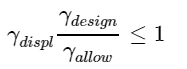
Equation 3: Allowable displacement
Where
γdesign :Estimated lateral displacement during the design storm
γallow :Allowable lateral displacement
γdispl :Safety factor for stability
Safety factors
The safety factor γabs are presented in 3.6.3 in [201] is based on:
- Representative region (North Sea/ Gulf of Mexico or Southern ocean)
- Storm type (Winter storm or cyclonic)
- Soil type (sand/rock / clay)
- Safety factor (Low /mid/ high)
Guidance note:
– For global locations, North sea regulations are recommended.
– Winter storm is normally observed in North Sea
– It is generally conservative to use High safety factor as the factor is suitable for pipelines. Since the burial proportion of the cable is higher, the safety factor is recommended to be low to mid (based on offshore post lay observations.
Design environmental conditions
The as-laid cable is subjected to a design wave generated load. The characteristic load condition shall reflect the most probable extreme response over a specified design time period.
For permanent operational conditions and temporary phases with duration in excess of 12 months, a 100-year return period applies, i.e. the characteristic load condition is the load condition with 10-2 annual exceedance probability. When detailed information about the joint probability of waves and current is not available, this condition may be approximated by the most severe condition among the following two combinations:
1) The 100-year return condition for waves combined with the 10-year return condition for current.
2) The 10-year return condition for waves combined with the 100-year return condition for current.
For a temporary phase with duration less than 12 months but in excess of three days,
a 10-year return period for the actual seasonal environmental condition applies. An approximation to this condition is to use the most severe condition among the following two combinations:
1) The seasonal 10-year return condition for waves combined with the seasonal 1-year return condition for seasonal current.
2) The seasonal 1-year return condition for waves combined with the seasonal 10-year return condition for current.
Make sure that the season covered by the environmental data is sufficient to cover uncertainties in the beginning and end of the temporary condition, e.g. delays.
For a temporary phase less than three days, an extreme load condition may be specified based on reliable weather forecasts. The method is summarized in the image below.
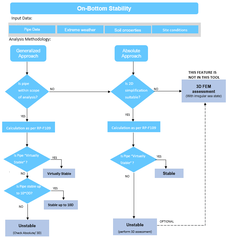
Generalized method
Concept
The methodology is based on empirical curves created using various experiments on pipelines. If the cable or pipeline has the specific gravity within limits as prescribed by this method, the cable/pipe is comparable to the tested range. This is a 2D analysis.
The method is based on non-dimensional parameters such as:
K : Keulegan Carpenter Number
L : Weight parameter
M : Steady to oscillatory ratio (Current / Wave)
N : Spectral acceleration factor
Various combinations of K,M,N which account for “Force Contributors”, which are compared against “Resistance Contributing” numbers such as L for two soil types (Sand or clay).
Applicability and limitations
The generalized stability assessment was originally developed for pipelines. The advantage is that it is empirically developed based on actual tests, hence it is quite reliable. Since the influence of bend stiffness and end effects are not considered, the guideline can be applied to cables.
However, the cable must be within following parametric limit.
- Specific weight (sg) is above 1.05
- Environment parameters requiring sg of 3.0 for cable to be stable.
- No penetration is considered
Often the array cables/light pipes do not comply with the stability regime of this method.
Absolute method
Concept
The form of stability is based on force balance between external force and resistance. Due to weight and soil. If the force balance is within the criteria, then the cable is STABLE, else unstable. Both vertical and horizontal stability is assessed.
Formulations are presented in Equation 1 and Equation 2.
The peak horizontal and vertical forces are presented in Equation 6.
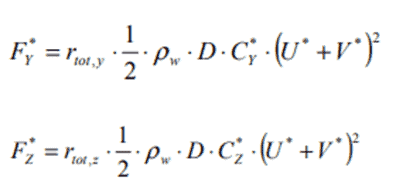
Equation 6: Peak horizontal and vertical excitation load
Where
ρw : Density of water
Cy, Cz : Peak load coefficients (Table 3.9 and Table 3.10 of [201])
rtot : Reduction factor
The force has the form of drag force exerted on the seabed. However, this is not Morison based drag formulation as the coefficients of drag are not applicable to near-seabed conditions. Hence the “coefficients of forces” are evaluated for near-seabed conditions.
Applicability and limitations
The method can be used only if the 2D analysis shows instability. Also, for a highly sloped seabed, where the assumption of a flat seabed is not possible, 3D analysis can be used. It is also possible that the cable after displacement can land into a trench which can lead to stability. These can be observed in the 3D analysis.
However, as mentioned before, the displacement is not based on open water hydrodynamic drag and thus the application of software like OrcaFlex is not suitable. The result is only indicative. Secondly the process of analysis is quite time-consuming.
Also, in the decision-making process, it is recommended to focus on displacement mitigation measures instead of detailed analysis, as the results are not optimistic as per experience.
Usage of the calculation tool
The tool combines both formulations into simple outputs for the initial decision of the pipe layer. Usually the pipe/cable field has multiple kilometers of laid distance. This tool can be used to quickly identify the most critical locations in the field to perform a detailed analysis using 3D approach. The calculation can be done very quickly and the selection of the most critical laid pipe can be done in seconds.
Note that DNV-RP-F109 may not be useful in every soil type and slope, and therefore a detailed analysis is to be done. There are multiple papers presented in international forums where a more site-specific analysis needs to be done, taking into account the bathymetry or soil displacement (like erosion and sedimentation, self-burial, soil liquefaction) These calculations must be done on a very detailed scale using CFD tools. However such exceptional conditions occur on a much smaller scale than majority of cables laid in fields.
Also note that DNV-RP-F109 is a constantly evolving recommended practice that takes note of newer exploration and site experiences from the asset owners. We at TheNavalArch would keep updating the versions keeping an eye on the developments from DNV.
Disclaimer: This post is not meant to be authoritative writing on the topic presented. thenavalarch bears no responsibility for the accuracy of this article, or for any incidents/losses arising due to the use of the information in this article in any operation. It is recommended to seek professional advice before executing any activity which draws on information mentioned in this post. All the figures, drawings, and pictures are property of thenavalarch except where indicated, and may not be copied or distributed without permission.
Why the bollard pull calculation method for a barge won’t work for a ship
In my working with the marine transportation industry for more than a decade now, I have come across many different calculations for required bollard pull for both barges and ships. The principles of the calculation are same, whether it is a ship, a barge...
STEEL COILS LOADING – ITS CHALLENGES AND WAYS TO OVERCOME
STEEL COILS LOADING – ITS CHALLENGES AND WAYS TO OVERCOME by Mr. Spiros Malliaroudakis (Founder & Managing Director, S.A. Malliaroudakis Maritime (UK) Ltd) The loads derived from steel coils loading are very concentrated, leading to higher stresses...
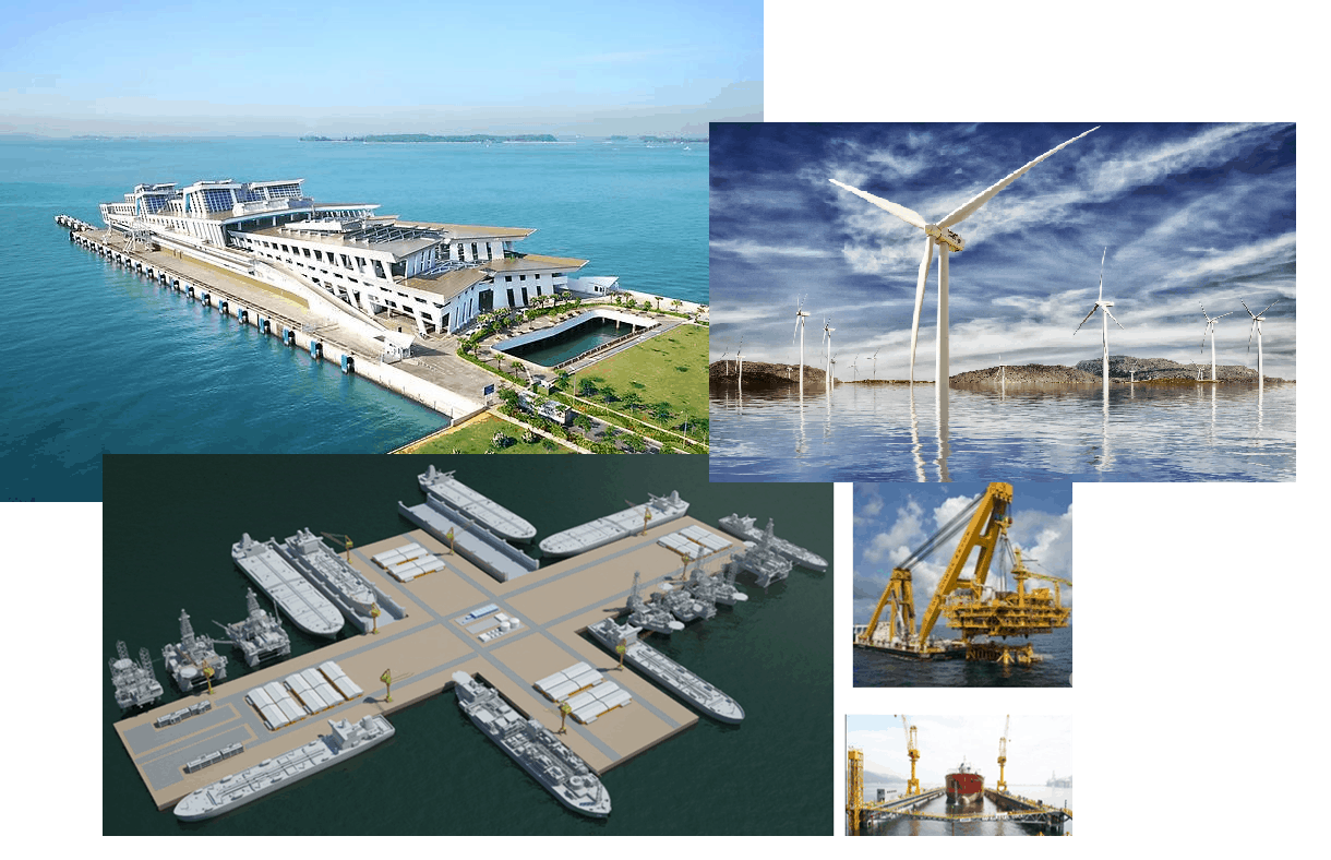
Naval architecture, new challenges and a new horizon
Naval architecture, new challenges and a new horizon by Lim Soon Heng, BE, PE, FSSS, FIMarEST Founder President, Society of FLOATING SOLUTIONS (Singapore) Civilization has arrived at a point of inflexion triggered by global warming and rising sea levels....
Mooring System Design and Analysis
Mooring System Design and Analysis by Rahul Kanotra, Consultant Naval Architect As the offshore industry moves towards greater technological advancements, one thing that has plagued the engineers is the “plug and play” computer programs or software. I am not against...
Cargo Stoppers – why they are critical and how to design them
Stoppers and their critical role in seafastening of cargo Introduction A cargo transported on the deck of a ship is subject to many forces. These forces comprise of the inertial forces due to the ship motions – the three translations and three rotations – and the...
Are you chartering a tug bigger than necessary for your Barge?
Barges are one of the most frequently used means for transporting deck cargo of different shape, size and weight. While some barges are self-propelled, the majority is towed by another vessel called a ‘Tug’. Once an owner or charterer...
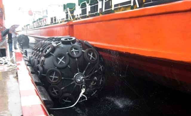
Fendering – an Introduction
In this two part article we will talk about Fendering, which is one of the basic but critical operations related to a ship. Fendering is, basically, protecting the ship’s sides from contact with another body (which can be another ship, jetty or quay wall). It can also...
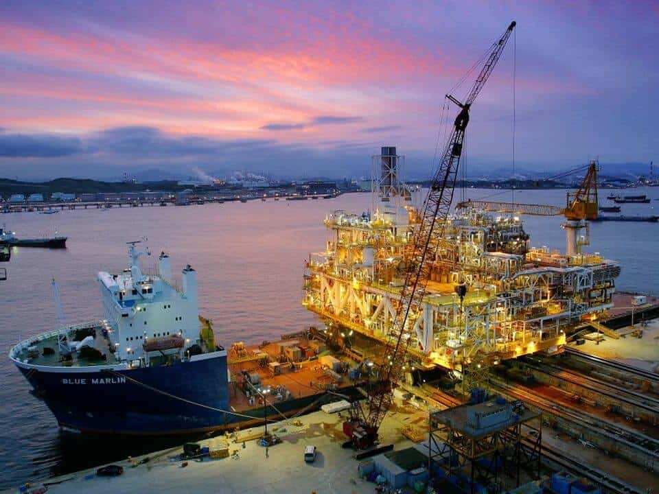
Loadouts – An introduction
Image source: Flickr Loadout Operations - an Introduction Loadout is a term oft heard of in the marine/offshore industry parlance. Loadout is generally referred to the operation of transferring a Cargo or a Structure from the place of fabrication to a sea-borne...
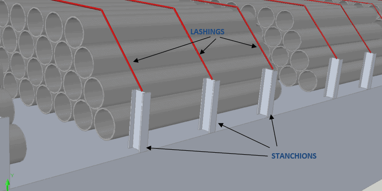
Introduction to Pipe Transportation – Part 3 (Engineering)
Introduction to Pipe Transportation - EngineeringIn Part 1 we learnt about pipes, while in Part 2 we learnt about Planning and Scheduling of pipe transport operations. In this part, we will learn about Engineering.Phase 3 – Engineering.Engineering for pipe...
Introduction to Pipe Transportation – Part 2 (Planning & Scheduling)
In Part 1, we looked at the properties of pipes. In this section, we will be looking at the Planning & Scheduling of a pipe transportation operation (see below, Phase 1 & 2) SECTION 2: PLANNING, SCHEDULING, AND ENGINEERING FOR A PIPE TRANSPORT PROJECT Source:...
