In this article, we will explore three simple but useful calculations that can be used for towing operations. They are:
- Towline Stiffness
- Propeller race
- Towing bridle force
DNV-RP-H1o3, Modelling and Analysis of Marine Operations, FEBRUARY 2014 has been referenced extensively for this article.
Towline Stiffness:
The first calculation is that of the stiffness of the towline. The towline can be considered like a spring that stretches and contracts as the distance between the tug and the towed object varies. Stiffness of the towline measures how much the towline will stretch under a given tension. A stiff towline will stretch lesser compared to one with low stiffness. This is governed by the spring equation F = kδ, where F is the force (tension) in the towline, while δ is the displacement (or stretch) of the towline.
How do we calculate the towline’s stiffness?
The stiffness of a towline is affected by two important factors:
- The elastic elongation of the line – this is the stiffness that depends on the material properties of the towline, and also on the dimensions of the towline. This is given by
kE = E x A/L, where
A = nominal cross-sectional area of towline [m2]
E = modulus of elasticity of towline [N/m2]
L = length of towline [m]
- Change in towline geometry – during the tow, as the tension in the towline varies, the catenary of the towline will also vary and this change in catenary leads to a change in the stiffness of the line. The formula for this change is given by
kG = 12 To3/{(wL2)L}, where
TO = towline tension [N]
w = submerged weight per unit length of towline [N/m]
L = length of towline [m]
The total elongation of the towline is a sum of the individual elongations due to the two factors: elastic elongation and change in geometry. Thus, these two effects are equivalent to putting two springs in series, as below [Ref 2]
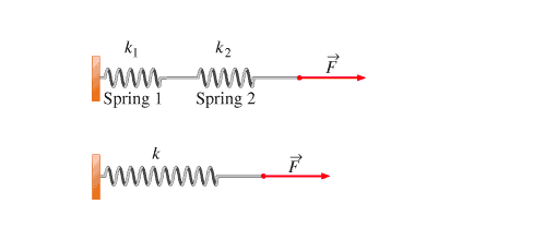
Fig 1 – Springs in Series, k = k1k2/(k1 + k2)
The resultant stiffness for two springs in series is given by
k = kGkE/(kG + kE)
It can also be re-written as
k = kE/(1 + kE/ kG)
If the towline tension is high, then kG will be high, and the stiffness will largely be contributed by the elastic stiffness kE
Generally, the spring equation F = kx is valid only when the motion of the towline is a undamped motion devoid of any wave frequency motions. If dynamic effects like added mass, wave motions or damping are to be added, then the above equation needs to be modified, and the stiffness shall have to be calculated from a full-fledged dynamic analysis.
Propeller Race:
The propeller race is the disturbance created by the propeller of the tug in its wake. This disturbance leads to an increase in the flow velocity of water around the towed structure. Due to the increased flow velocity, the towed structure experiences a higher drag. This increased flow velocity is called the ‘propeller race’, and its impact on the towed object can be analyzed depending on the length of the towline deployed.
- For towlines that are short (typically less than 30 m), and for smaller towed objects, the effect of the propeller race can be calculated by calculating the additional drag on its structural members due to the propeller race. The propeller race is a velocity profile which varies with the distance aft of the propeller, and also radially from the center of the propeller. Looking at the figure below:
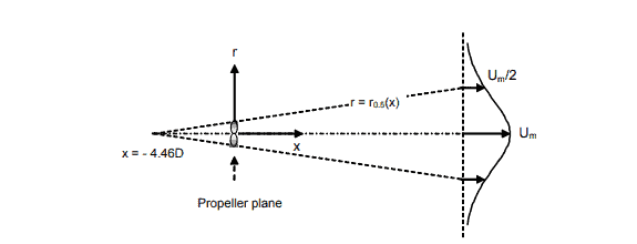
Fig 2 – Propeller Race profile [Ref 1]
We can see that the propeller race is modeled as a jet of water which starts from a distance -4.46D fwd of the propeller (i.e., towards the tug), where D is the diameter of the propeller. This jet expands with increasing distance towards the aft of the propeller (i.e., towards the towed object). The term Um is the maximum flow velocity at a distance of ‘x’ meters towards the aft of the propeller. The maximum velocity at any location occurs radially at the point where the longitudinal axis cuts the velocity profile. As we go away from the center, the velocity reduces. Thus, the velocity profile depends on both the longitudinal distance (x) and the radial distance (r) of a point behind the propeller. The equations governing the velocity profile are given below:

In the above equation, U0 is the flow velocity through the propeller disc, and D is the diameter of the propeller disc.
- When the towline length is more than 30 m, there is a simpler way of estimating the effect of the propeller race. Since the propeller race increases the drag on the towed object, in effect, it reduces the available bollard pull of the tug. This reduction in the available bollard pull of the tug can be calculated by a factor called ‘interaction efficiency factor’, αint which is a function of the size of the propeller, the length of the towline, and also the type of vessel.
For barge-shaped towed objects, the ‘interaction efficiency factor’ is given by
αint = [1 + 0.015 Aexp/L]-η
αint = interaction efficiency factor
Aexp = projected cross sectional area of towed object [m2]
L = length of towline in meters [m]
η = 2.1 for typical barge shapes
Thus, if the bollard pull of the tug is BP, then the available bollard pull shall be
BP(available) = BP x αint
Towing Bridle Force Calculation:
The last topic we’ll talk about in this article is the calculation of the force on the lines of a Towing Bridle. Generally, when both the tug and the towed object are oriented in the same line, the forces in the two lines of the towing bridle are expected to be the same.
This is shown in the figure below. The tension in each bridle leg is T’ = T0/ (2 cosβ)
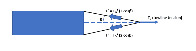
Fig 3 – an evenly loaded towing bridle
What if the towline and the towed object are not in the same line, and the towed object is rotated at an angle to the towline? This scenario is shown below:
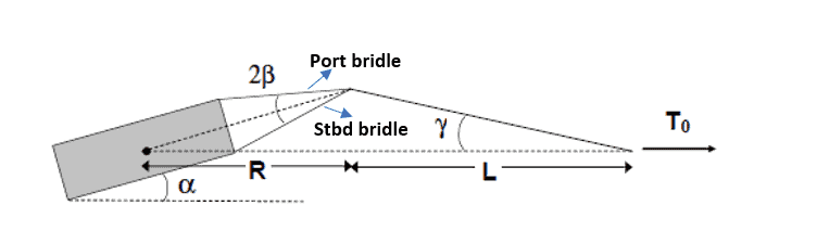
Fig 4 – An asymmetrically loaded towing bridle {Ref 1]
We can see that the towline makes an angle of γ to the axis connecting the Center of Gravity of the towed object with the end of the towline. The towed object itself makes an angle of α to the horizontal.
Some points worth observing here are:
- In the configuration shown above, the port bridle will take a higher load, while the Starboard bridle will take a lesser load
- As the angle α keeps increasing, gradually the force in the Stbd bridle will become zero, after which it will go slack. From that point on, the port bridle takes all the load.
- For small values of the angle γ, the forces in the two bridles can be given by the following formulae:
- We can see from above that the force T2 in the Stbd bridle will become zero when
sin (β – α – γ) = 0
=> β = α + γ = α (1 + R/L)
=> α = Lβ/ (L + R)
- The towing force also creates a moment about the center of gravity of the structure. This moment provides additional stability to the tow and demonstrates the significance of towing bridles. This is given by
MG = T0Rβ
=> MG = T0R(1+R/L) α
That brings us to the end of this article. We hope you enjoyed reading it. Please do check out our related products below.
Disclaimer: This post is not meant to be authoritative writing on the topic presented. thenavalarch bears no responsibility for the accuracy of this article, or for any incidents/losses arising due to the use of the information in this article in any operation. It is recommended to seek professional advice before executing any activity which draws on information mentioned in this post. All the figures, drawings, and pictures are property of thenavalarch except where indicated, and may not be copied or distributed without permission.
Why the bollard pull calculation method for a barge won’t work for a ship
In my working with the marine transportation industry for more than a decade now, I have come across many different calculations for required bollard pull for both barges and ships. The principles of the calculation are same, whether it is a ship, a barge...
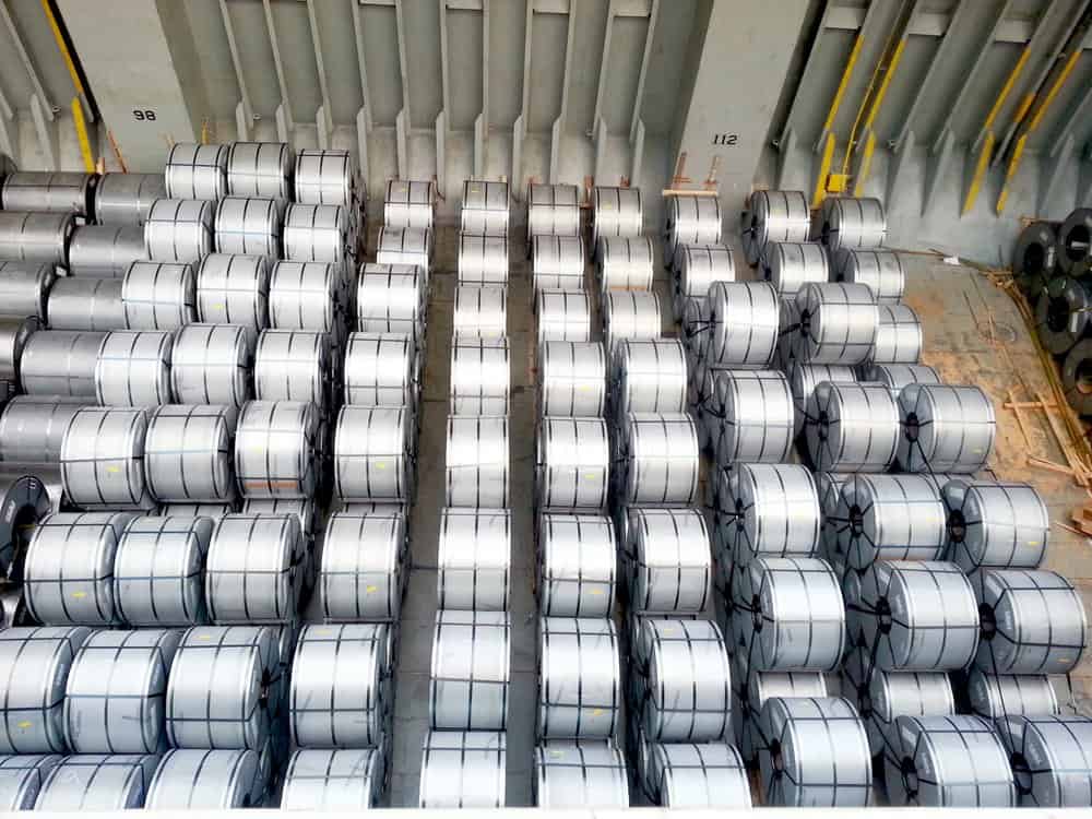
STEEL COILS LOADING – ITS CHALLENGES AND WAYS TO OVERCOME
STEEL COILS LOADING – ITS CHALLENGES AND WAYS TO OVERCOME by Mr. Spiros Malliaroudakis (Founder & Managing Director, S.A. Malliaroudakis Maritime (UK) Ltd) The loads derived from steel coils loading are very concentrated, leading to higher stresses...
Naval architecture, new challenges and a new horizon
Naval architecture, new challenges and a new horizon by Lim Soon Heng, BE, PE, FSSS, FIMarEST Founder President, Society of FLOATING SOLUTIONS (Singapore) Civilization has arrived at a point of inflexion triggered by global warming and rising sea levels....
Mooring System Design and Analysis
Mooring System Design and Analysis by Rahul Kanotra, Consultant Naval Architect As the offshore industry moves towards greater technological advancements, one thing that has plagued the engineers is the “plug and play” computer programs or software. I am not against...
Cargo Stoppers – why they are critical and how to design them
Stoppers and their critical role in seafastening of cargo Introduction A cargo transported on the deck of a ship is subject to many forces. These forces comprise of the inertial forces due to the ship motions – the three translations and three rotations – and the...
Are you chartering a tug bigger than necessary for your Barge?
Barges are one of the most frequently used means for transporting deck cargo of different shape, size and weight. While some barges are self-propelled, the majority is towed by another vessel called a ‘Tug’. Once an owner or charterer...
Fendering – an Introduction
In this two part article we will talk about Fendering, which is one of the basic but critical operations related to a ship. Fendering is, basically, protecting the ship’s sides from contact with another body (which can be another ship, jetty or quay wall). It can also...
Loadouts – An introduction
Image source: Flickr Loadout Operations - an Introduction Loadout is a term oft heard of in the marine/offshore industry parlance. Loadout is generally referred to the operation of transferring a Cargo or a Structure from the place of fabrication to a sea-borne...
Introduction to Pipe Transportation – Part 3 (Engineering)
Introduction to Pipe Transportation - EngineeringIn Part 1 we learnt about pipes, while in Part 2 we learnt about Planning and Scheduling of pipe transport operations. In this part, we will learn about Engineering.Phase 3 – Engineering.Engineering for pipe...
Introduction to Pipe Transportation – Part 2 (Planning & Scheduling)
In Part 1, we looked at the properties of pipes. In this section, we will be looking at the Planning & Scheduling of a pipe transportation operation (see below, Phase 1 & 2) SECTION 2: PLANNING, SCHEDULING, AND ENGINEERING FOR A PIPE TRANSPORT PROJECT Source:...

I’m Captain and do towing and rescue all my life. I’m interested from any new knowladge.
Hi Capt Valentin
Thanks for your support!
How to calculate tow gear analysis from one point to another?
what a tugboat bollard pull needed to tow a dredger of 840GT and 65 LOA and draft 401
Thanks for serious explanations about towing
ans where can I fing the tree calculations , regarding towing !
As an ex Captain |Fairmount Marine i certinly would like to know
Rgs Karel
soy capitan de altura y capitan de puerto carupano venezuela, quisiera los calculos de remolque entre puertos oceanicos