In the world of advancing digital technology, it important to identify all the best ways to apply it to the extremely complex task of designing a ship. Riding the wave of the rapid progress of High Performance Computing, Computational Fluid Dynamics (CFD) has become an attractive tool for gaining valuable insight into hydrodynamic characteristics of surface vessels. CFD, or more specifically RANS based CFD methods, models the fluid flow with Navier-Stokes equations, accounting for their nonlinear nature, viscous and turbulent effects. It is a complete method in terms of physical modelling, where very little is left to assumptions. This allows it to be highly accurate and precise, but it also makes it very computationally expensive comparing to most engineering tools in the field. It also requires a highly skilled CFD specialist, preferably with a background in naval architecture. Needless to say, such individuals are expensive, hard to find, and can only do one thing – CFD for naval hydrodynamics. This is why CFD has not fulfilled its full potential in aiding the day-to-day, industrial ship design process, and still largely remains an advanced method used and developed in large scientific projects and R&D departments of multi-million-dollar companies. Smaller ship design companies simply have no resources or permanent need for a CFD specialist, and this is why they do not use it. So, the question is: how, when and where can CFD be useful in a realistic, industrial, everyday ship design process? Read more and find out.
Basics of CFD
In general, CFD stands for any computational method that has to do with fluid dynamics. In professional jargon, however, it usually denotes the family of methods that model the full Navier-Stokes equations, where the flow nonlinearities, viscosity and turbulence are included. The most wide-spread method in this family is the Finite Volume approach, which solves the integral form of flow equations by dividing the volume of the computational domain into many small finite volumes. Each finite volume is assumed to be small enough to allow the rate of change of any variable to be approximated with a linear function. These finite volumes are assembled into a computational grid, where one or more boundaries represent an object of interest, such as a vessel hull, an offshore platform, the inside of a pipe etc. Figure 1 shows an example of a discretized surface of an oil tanker.
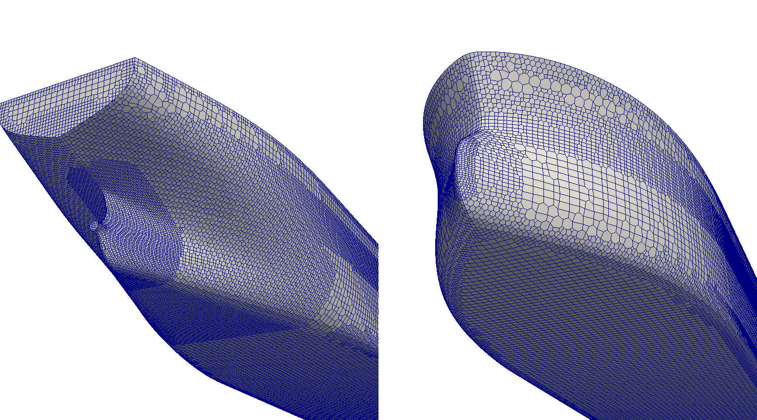
Fig 1 Computational grid of an Oil Tanker
It is typical in the field of computational naval hydrodynamics to model water and air as ideally incompressible fluids, since their compressibility has no or little influence on most problems in marine and offshore industry. In that case, the equations modelling the flow are as follows:
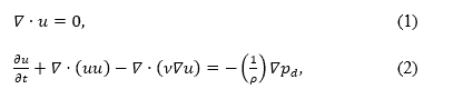
where the first equation represents the continuity equation, ensuring mass conservation, which reduces to conservation of volume for incompressible flow. It simply states that the volume of fluid going into a finite volume must be equal to the volume going out of the finite volume. The second equation denotes the conservation of momentum, otherwise known as the Navier-Stokes equations. This vectoral equation governs the rate of change of velocity taking into account the influence of viscosity, turbulence and pressure gradient.
Equations (1) and (2) make a closed system that governs the flow of incompressible fluid. However, what we need is to model two fluids at once: air and water. In order to do this, a method for describing the interface between these two fluids is needed, also known as the free surface. This is where a bit of diversity can be found among open-source and commercial software, since there is more than one way in which this can be done. The two most prominent methods are the Volume of Fluid (VOF) approach (Ubbink and Issa 1999), and the Level Set approach (Sussman 1994).
The Volume of Fluid approach is based on a liquid fraction variable (usually denoted with the Greek letter alpha, α) that states the percentage of the finite volume filled with water. For example, value 1 denotes that the finite volume is filled entirely with water, while 0 means it contains only air. If the value is 0.3, 30% of the volume is occupied with water and 70% with air. From this it follows that the location of the interface is at the iso-surface corresponding to the VOF value of 0.5.
The Level Set method works on another principle: here the interface is located by using a so-called distance function. The active variable in this method is the value of the distance function, denoting the distance of any point in space from the free surface. When the value is zero, the point must be located at the free surface itself.
The two methods have their respective advantages and disadvantages, which is why they both find their place in different simulations in naval hydrodynamics. For example, VOF is very conservative, meaning that the ratio of water and air in the simulation will be well preserved. This is important in simulations such as wave impacts, dam breaks, green water effects, sloshing etc. Generally, it is better at handling violent free-surface phenomena. The disadvantage is that it is prone to numerical smearing, where the thickness of the interface becomes unrealistically large which can influence the accuracy of the simulation. Even though various numerical tricks can be applied to reduce the effect of smearing (see e.g. interface compression approach in Rusche 2002, or ventilation suppression approach in Viola, Flay, and Ponzini 2012), this can still pose a serious problem in some simulations. The Level Set on the other hand, does not suffer from smearing, however it is non-conservative, meaning that some loss/gain of water can be expected. This is especially true for more violent free surface phenomena. It therefore comes naturally to use Level Set for simulations such as calm water resistance, self-propulsion, seakeeping and other simulations where the free surface remains relatively smooth, and where smearing would affect the accuracy. Figure 2 shows the comparison of the liquid fraction value α distribution on the surface of a planning vessel from Pigazzini et al. 2018, where a severe smearing is present in the VOF simulation.
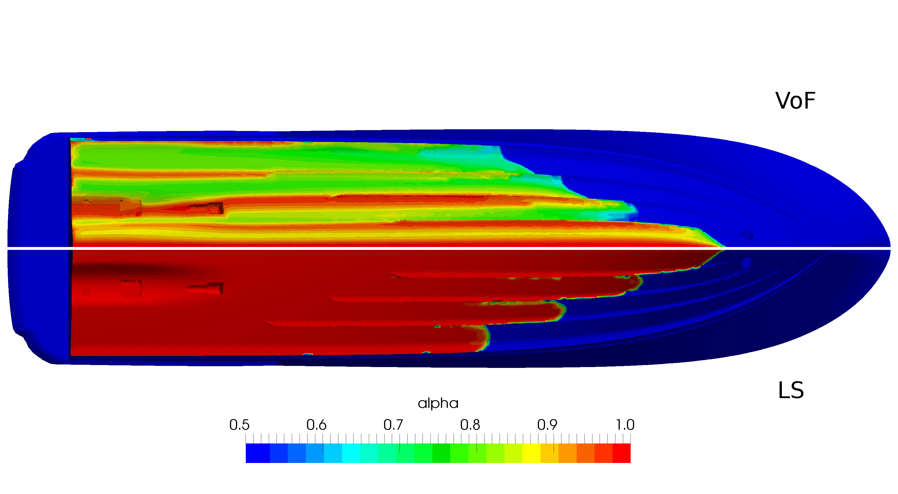
Figure 2: Comparison of the liquid fraction variable with the Volume of Fluid and Level Set method (Pigazzini et al. 2018).
CFD in practical ship design
In the process of ship design the basic hydrodynamic characteristics of the vessel need to be assessed early in the project in order to proceed along the design spiral. These basic characteristics are ship resistance in calm water and propulsion power. It is common practice to estimate these values using empirical methods such as the one proposed in Holtrop and Mennen 1982, or to use adjusted data from similar vessels. Both of these methods will give a very good estimate of resistance and required propulsion powering for most vessels if used properly. In the later stage of the project, towing tanks are hired to confirm the calculation and to provide more accurate results, which are otherwise too expensive to be included in the early design stage. The downside of this approach is that the designer has no way of quantifying the impact of smaller geometrical changes to the hull early in the design process (since these are not distinguished in empirical methods). This makes the designer more conservative and cautious, leading to less innovative designs, and often to over-dimensioned main engines.
CFD offers a method that could provide an accurate result early in the design stage, allowing the designer to try out different options easily and without large financial or temporal cost. I say “could” because this is often not the case. Conducting a CFD simulation is not straight forward and requires an expensive commercial software. Open-source CFD software also exist but are hard to use and require a specialized user. Lately, however, more and more companies offer consulting services where they conduct the simulations for design offices. This is an ideal set-up, fitting nicely into the idea of division of labor. The cost, quality and speed of these services are getting better and better, reaching a point where they can really be used in an early design stage.
As mentioned earlier, there are two main hydrodynamic problems that are of interest in a typical design process: the calm water resistance and self-propulsion characteristics. Calm water resistance is the first hydrodynamic property that is needed, usually across a range of vessels speeds. CFD simulations of calm water resistance are the basis of computational marine hydrodynamics, but that does not make them trivial at all. A high level of experience is needed to obtain a high-accuracy result: from grid generation, numerical setup to post-processing. With most modern CFD codes, accuracy within 3% can be expected for calm water resistance in full scale, for a computational cost of around 100 – 300 core-hours for a single simulation, which translates to around 10 – 30 EUR of hired HPC resources. This means that the simulation is finished after 2 – 5 hours of wall-clock time. This makes it easy to compare and test various ideas early in the design. Figure 3 shows an example of such an application of CFD in the design process, where three slightly different bow shapes are tested and compared in terms of total resistance and generated wave field.
Apart from integral quantities such as resistance, dynamic sinkage and dynamic trim, the wake contour plot in the propeller plane can be obtained with a bit of extra post-processing. Figure 4 shows a wake field contour plot in the propeller plane, obtained from a calm water resistance CFD simulation.
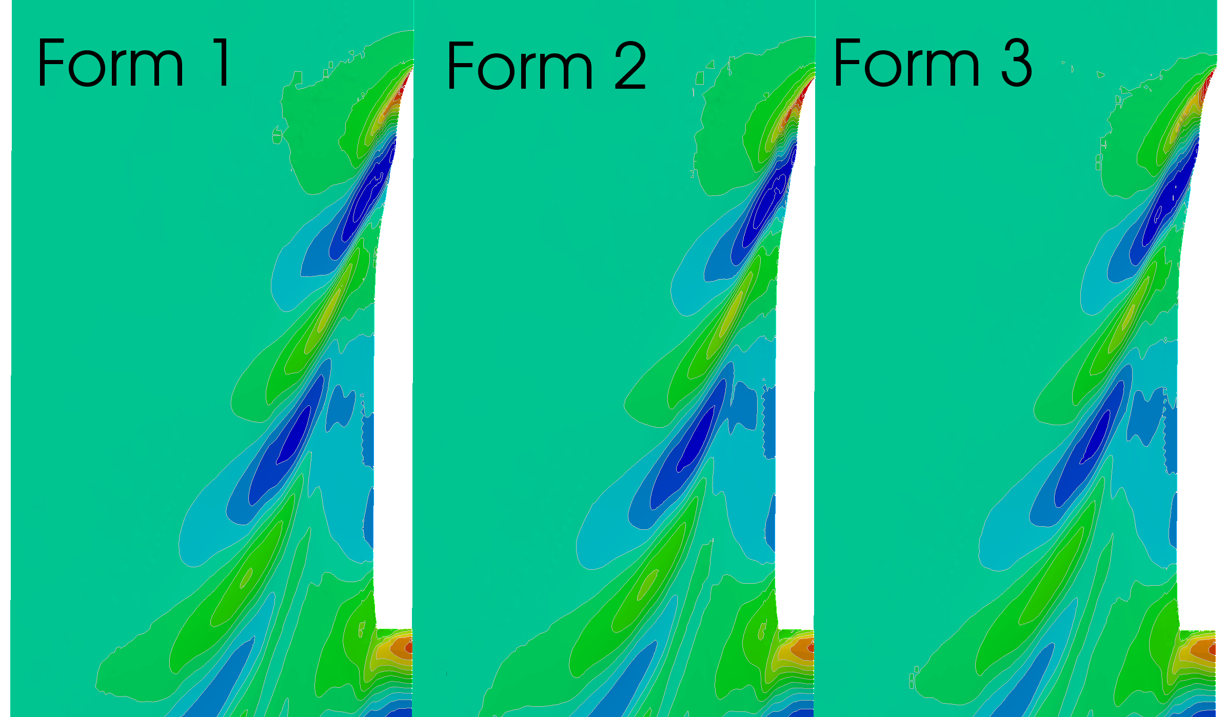
Figure 3: Comparing the wave field of three bow designs.
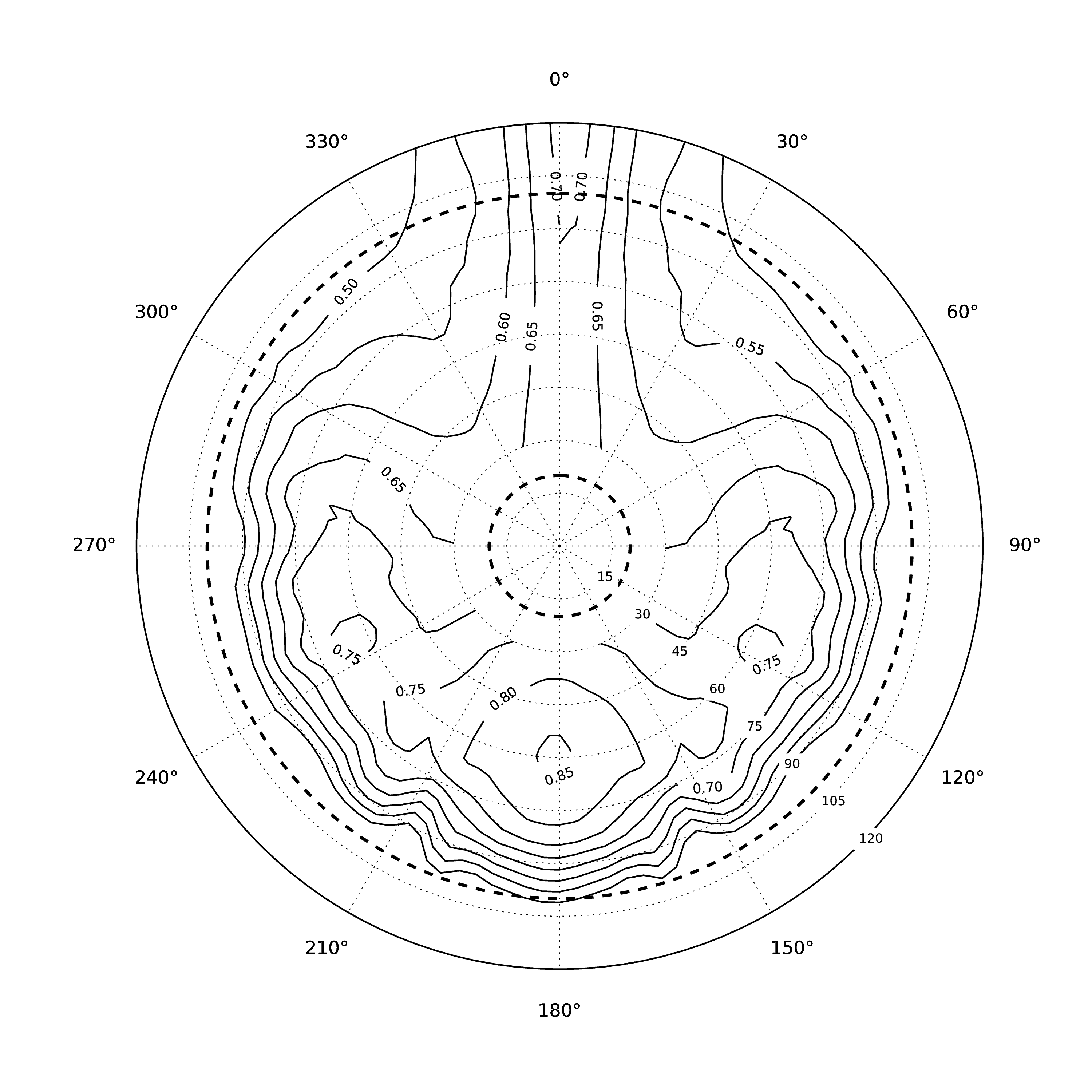
Figure 4: The ship wake field in the propeller plane
Self-propusion test provides information about the required shaft power delivered to the propeller at certain load condition and speed. It is, therefore, more complex than the calm water resistance simulation since the propeller needs to be included in some way. There are two main ways to include the propeller action in a CFD simulation: I) full geometrical representation of the rotating propeller; II) simplified model of the propeller, based on the actuator disc theory. For a typical selfpropulsion simulation, the actuator disc model is sufficient, as it will give the integral properties such as thrust and torque correctly, and it will result in a water jet behind the propeller impacting the rudder, which is important for the overall ship resistance. The full geometrical representation of the rotating propeller is extremely expensive due to separation of temporal scales between the propeller rotation and the flow features around the hull. This yields a high CPU demand that is seldom justified for self-propulsion simulation, and is reserved for more advance studies such as propeller noise and vibration analyses, vortex formation etc.
A typical self-propulsion CFD simulation with an actuator disc model takes a similar amount of CPU resources comparing to calm water resistance simulation, but it takes more time and effort to set-up. Figures 5 and 6 show a self-propulsion simulation of a single screw car-carrier, and a two-screw naval vessel, respectively. Here, the actuator disc propeller model can be seen as a circular surface where the propeller action is applied by specifying a pressure jump corresponding to the required thrust (Jasak et al. 2018).
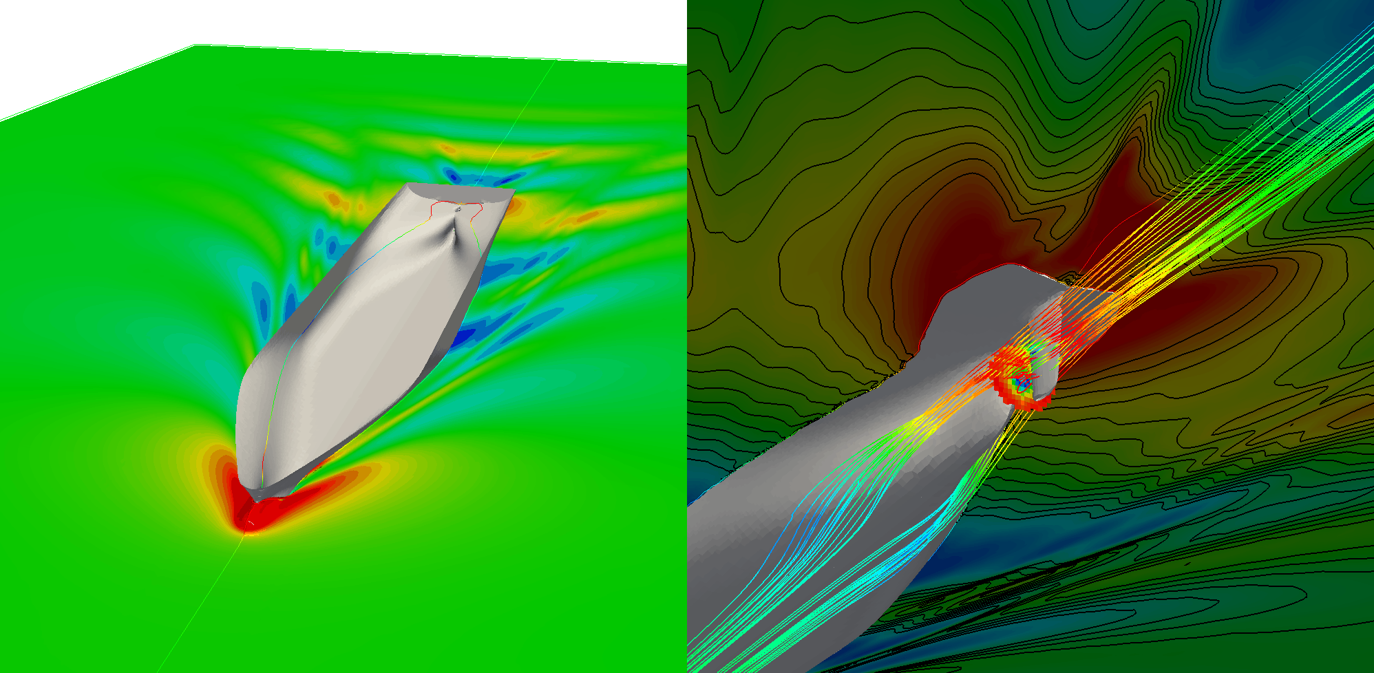
Figure 5: Self-propulsion simulation of a car-carrier
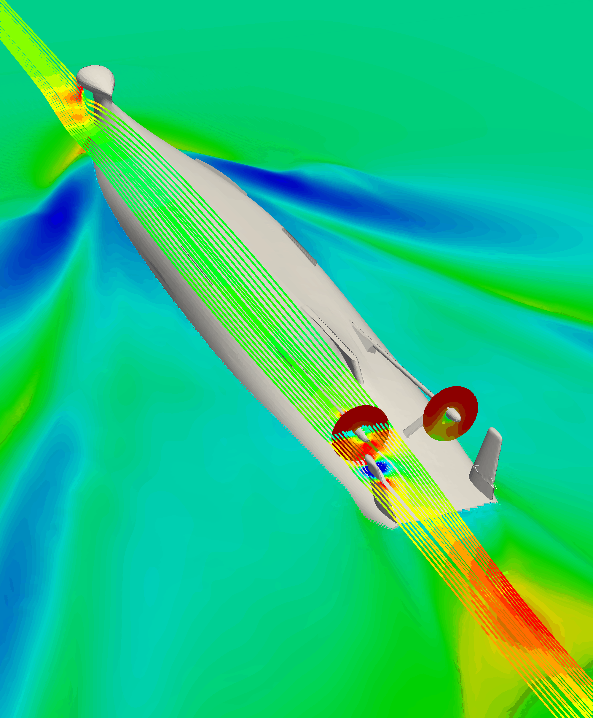
Figure 6: Self-propulsion simulation of a two-screw naval vessel
Advanced CFD simulations
Apart from the two types of simulations described above, there is a plethora of other problems present in naval and offshore hydrodynamics that can be tackled with CFD. Extreme wave impacts, green sea loads, slamming, sloshing, seakeeping, flooding, coarse-keeping, maneuvering, just to name a few. The property of CFD that allows it to be used on such a wide range of applications is the generality of the method. At the base level CFD does not hold any presumptions about the flow phenomena at hand, such as assumptions about the wave steepness, single-valued free-surface elevation, irrotational flow, small changes in the wetter surface of the hull and so on. This allows the method to be applied to many different problems, although difficulties can be expected in uncharted waters, i.e. phenomena which has not been simulated before.
Below are a few figures showing some of the phenomena that can be simulated using CFD. Figure 7 shows an image from a simulation of a crabbing maneuver. The ship has two rudders deflected to full starboard, the two propellers working in the opposite directions: port side propeller is running full ahead, and the starboard side full astern. The bow thruster is pushing the bow in the port side direction, resulting in a sideways motion of the vessel called crabbing. Figure 8 shows a green water event impacting a breakwater of a container vessel. These simulations serve as input for pressure loads in a FEM analysis of the breakwater structure, or any deck structure in general. In Figure 9 a simulation of a course keeping experiment is shown with two moving rudders and two propellers. The autopilot is instructed to keep the vessel on a steady course in heavy stern-quartering waves. The simulation presented in Figure 10 is conducted to analyze the effect of a passing 40-meter motor yacht on the vessels moored in the mini-marina.
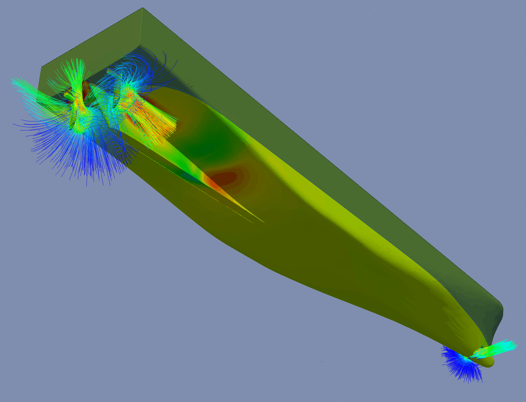
Figure 7: Simulation of a crabbing manoeuvre
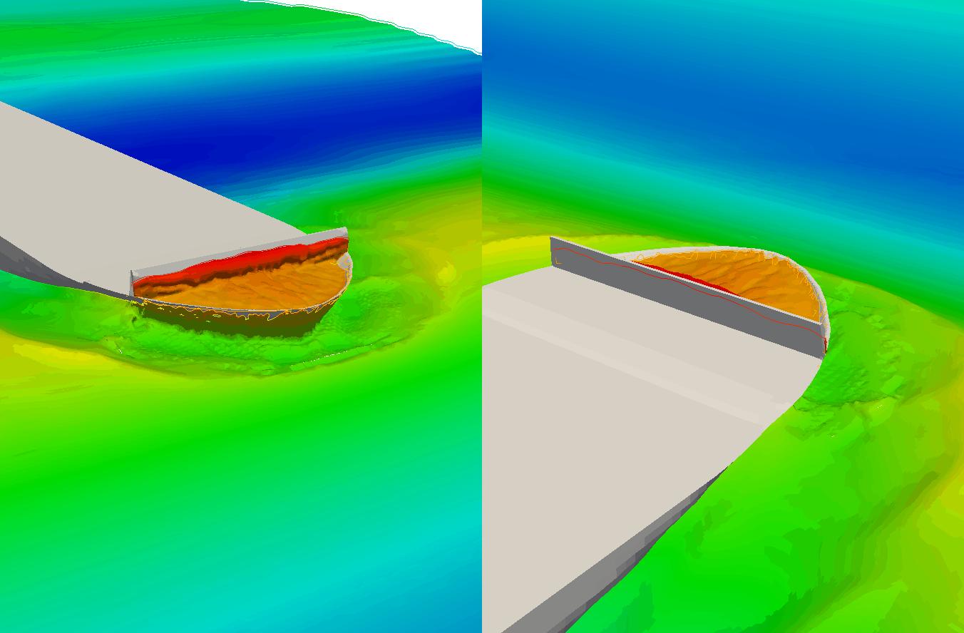
Figure 8: Green water event simulation on a container vessel
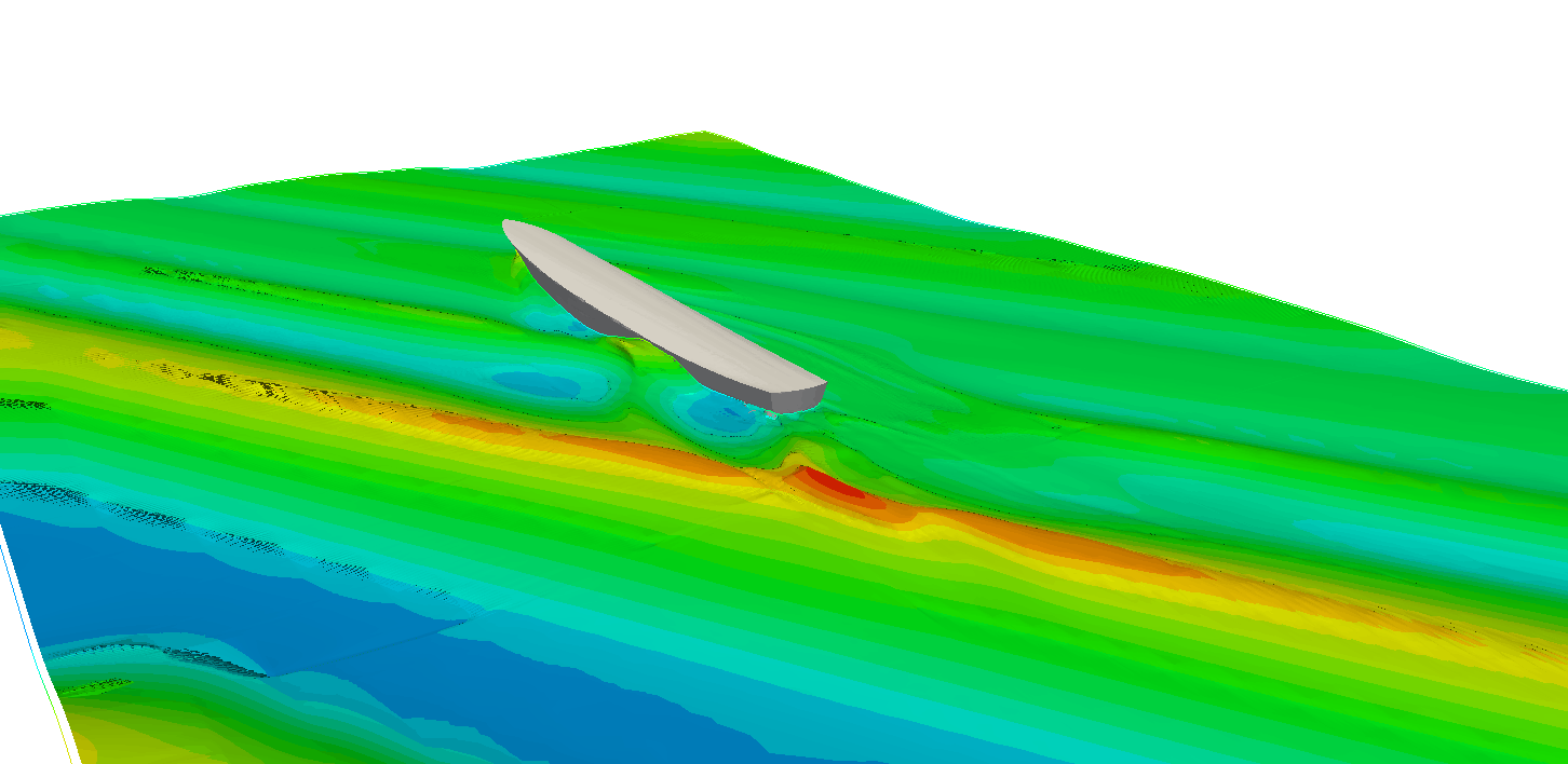
Figure 9: Course keeping simulation with dynamic rudders and PID controllers in heavy weather conditions
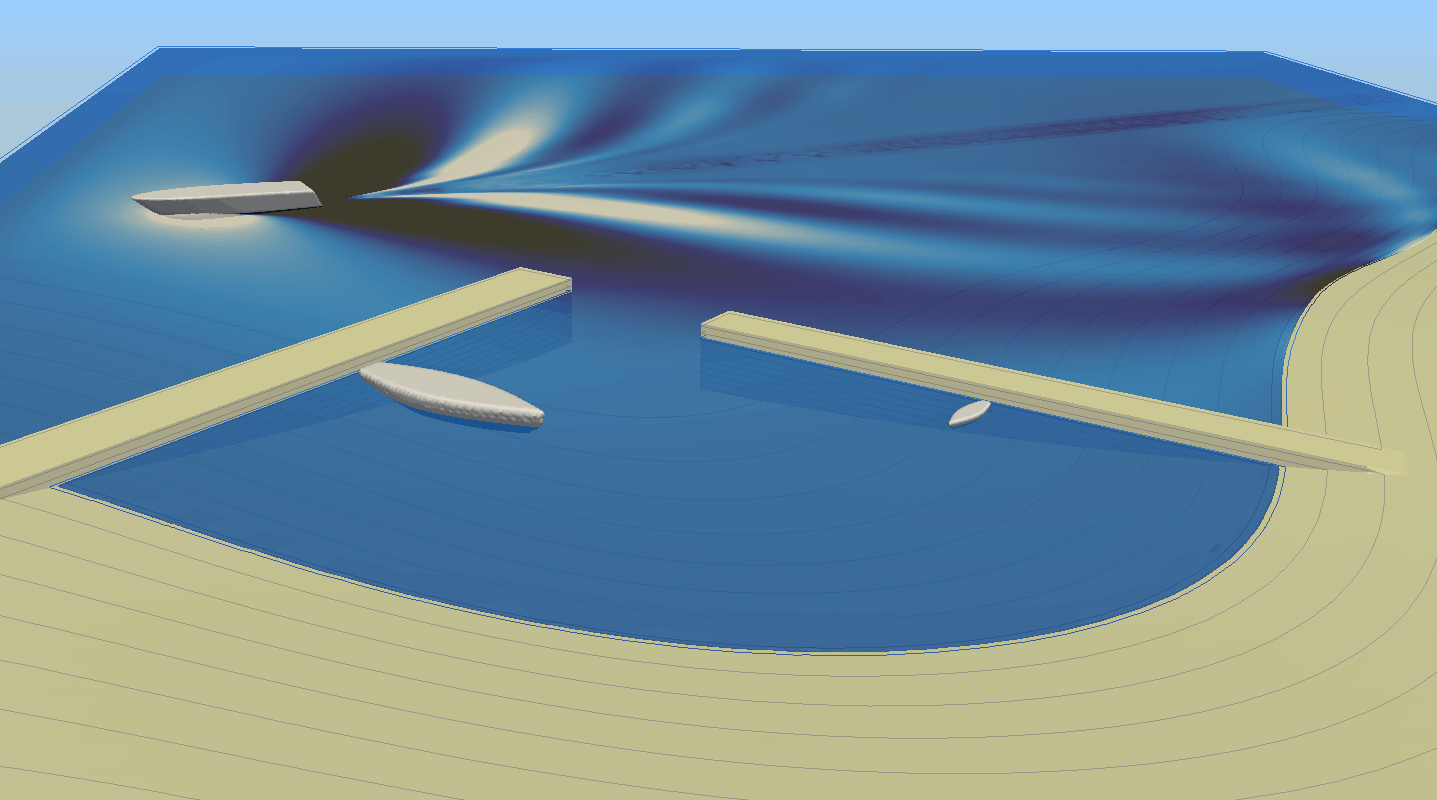
Figure 10: Study of the effect of a passing vessel on the wave field in-side of the marina
Conclusion
Computational Fluid Dynamics is a versatile and very powerful engineering tool which can offer an unprecedented level of detail of various flow phenomena. At the same time, however, it is highly complex to use and demands relatively large amounts of CPU resources comparing to most engineering tools. As technology progresses, the CPU resources become less expensive by the minute, eliminating the latter issue. As we mentioned earlier, a calm water resistance CFD simulation can be performed for as little as 10 – 30 EUR of HPC hire costs, rendering it accessible to most companies in the industry. The issue, however, is in the complexity of the tool, which unlike the cheapening of CPU resources, has not reduced with the advancement of technology. This entails a human resource problem, namely it is not easy to find experts in CFD for naval hydrodynamics, not to mentioned the cost of such employees. It is therefore not surprising that very little CFD is being used in day-to-day ship design projects. It is for this reason that we see an uptake of consultancy companies offering CFD simulation services for the marine industry, which could prove to be exactly what is necessary for this sort of tool to be widely applied.
The two most valuable calculation types that CFD can offer to the marine industry are the calm water resistance simulations and sefl-propulsion simulations. Using CFD to determine calm water resistance and propulsion power could completely revolutionize the way ships are designed, by giving an opportunity to obtain high accuracy results early in the design process. Advanced CFD simulations such as wave loads, maneuvering, seakeeping, green water simulations and others also find their place in more complex and expensive projects, offering a deeper insight about complex phenomena important for the efficiency and safety of marine objects.
References
Holtrop, J., and G. G. J. Mennen. 1982. “An Approximate Power Prediction Method.” International Shipbuilding Progress. https://doi.org/10.1007/s13398-014-0173-7.2.
Jasak, Hrvoje, Vuko Vukčević, Inno Gatin, and Igor Lalović. 2018. “CFD Validation and Grid Sensitivity Studies of Full Scale Ship Self Propulsion.” International Journal of Naval Architecture and Ocean Engineering, 2018. https://doi.org/10.1016/j.ijnaoe.2017.12.004.
Pigazzini, Riccardo, Thomas Puzzer, Simone Martini, Mitja Morgut, Giorgio Contento, Inno Gatin, Vuko Vukčević, et al. 2018. “Experimental and Numerical Prediction of the Hydrodynamic Performances of a 65 Ft Planing Hull in Calm Water.” In NAV International Conference on Ship and Shipping Research. https://doi.org/10.3233/978-1-61499-870-9-480.
Rusche, Henrik. 2002. “Computational Fluid Dynamics of Dispersed Two-Phase Flows at High Phase Fractions.” PhD Thesis. https://doi.org/10.1145/1806799.1806850.
Sussman, Mark. 1994. “A Level Set Approach for Computing Solutions to Incompressible Two-Phase Flow.” Journal of Computational Physics. https://doi.org/10.1006/jcph.1994.1155.
Ubbink, O., and R. I. Issa. 1999. “A Method for Capturing Sharp Fluid Interfaces on Arbitrary Meshes.” Journal of Computational Physics. https://doi.org/10.1006/jcph.1999.6276.
Viola, I. M., R. G.J. Flay, and R. Ponzini. 2012. “CFD Analysis of the Hydrodynamic Performance of Two Candidate America’s Cup AC33 Hulls.” Transactions of the Royal Institution of Naval Architects Part B: International Journal of Small Craft Technology. https://doi.org/10.3940/rina.ijsct.2012.b1.113.
Disclaimer:
The views, information, or opinions expressed in this article are solely those of the author and do not necessarily represent those of TheNavalArch Pte Ltd and its employees

Inno Gatin
CFD Consultant and Engineer, Wikki Ltd.
Dr. Inno Gatin is a naval architect specialized in computational naval hydrodynamics, with an academic and commercial experience in CFD modelling, development, consultancy and simulation services. During his academic work he performed research and development related to CFD models dedicated to extreme wave loads during events such as green water, sloshing and slamming. He also dedicated a large part of the academic career to calm water and self propulsion calculations, as well as seakeeping studies. Working as a CFD consultant and engineer for Wikki Ltd., he is involved in development, maintenance and support of the Naval Hydro Pack, the in-house CFD software for naval hydrodynamics. Together with his colleagues he invested considerable effort in automating basic CFD simulations for the marine industry, with the goal to democratize its application. He can be reached at i.gatin@wikki.co.uk.

Combating rising seas with floating structures
Introduction Rising sea level is an existential threat for many coastal cities. The sea is rising...
How to identify the spoolpiece lifting points?
In the offshore construction industry, the connection between the newly installed pipeline and the...
The importance of clear decision support before marine operations
Our oceans are interspersed with human activities: be it fishing, marine transportation, or...
Sea Pressure Loads Calculation based on DNV Rules
Introduction Sea pressure loads are an important factor in the structural design of a...
A quick empirical method for resistance estimation of planing vessels
Resistance estimation for a vessel is a fundamental exercise in design of the vessel. Resistance...
Powering the maritime industry with Hydrogen – Part 2
Powering the shipping industry with hydrogen - Part 2: Hydrogen propulsion on a ship -...
A simplified method of performing fatigue analysis of offshore structures
A simplified method of performing fatigue analysis of offshore structures Introduction An...
Powering the shipping industry with hydrogen: opportunities and challenges (Part 1)
Part 1: About Hydrogen – Basics, Opportunities, and Challenges Of late, hydrogen has been...
The importance of analysis in nearshore pull-in operation in offshore wind farms
Introduction Over the last 10 years, the global wind energy business has increased manifold. In...
Vessel Draft Survey Accuracy
by Chris Zeringue, Owner, MTS Marine Techincal Surveyors ...
I work with Openfoam for Windschip Project What do you think about lift/drag coefficients witch you can use to construct a polardiagram. The polardiagram is needed in weather routing programs.
Making a polar diagram using CFD is certainly a good way to go. These are relatively straight forward single-phase simulations, where good results can be obtained in reasonable time given that turbulence modelling is performed correctly. RANS is the best option, while LES or DES simulations required excessive CPU resources, while the effect on the accuracy of integral quantities such as drag and lift is negligible.
Dear Inno
Thanks for a great overview of the possibilities of CFD within the marine industry and a great analysis of why its use is currently not that widespread.
I have a remark/question regarding the pro’s and con’s you mention for VOF and Level Set. You write: “The disadvantage ()is that it is prone to numerical smearing, where the thickness of the interface becomes unrealistically large which can influence the accuracy of the simulation. Even though various numerical tricks can be applied to reduce the effect of smearing (see e.g. interface compression approach in Rusche 2002, or ventilation suppression approach in Viola, Flay, and Ponzini 2012), this can still pose a serious problem in some simulations.”
Wouldn’t you agree that this smearing problem only relates to algebraic VOF methods – not geometric VOF methods (such as isoAdvector) which by construction give a sharp interface? It would be quite interesting to see for instance your Fig. 2 using isoAdvector.
Best regards,
Johan
Dear Johan,
What you say is certainly true, and the statement you quoted is not doing justice to geometric VOF methods. I should’ve be more precise by specifying that this applies to algebraic VOF, and not geometric. The algebraic VOF methods are so widespread and commonly used that the adjective “algebraic” is often omitted in conversational language.
We have done a number of studies using isoAdvector and found it very useful for violent free surface flows such as wave impacts, green water, slamming etc. The sharpness of the free surface is immaculate and provides high quality results.
We have also tried using isoAdvector for planning hulls as this would certainly give an advantage, but found that the explicit nature of geometric methods in general makes it difficult to apply them to high speed craft cases such as this one. The reason is that CFL number we use in these sort of simulations is in the range of 20-100, which requires sub-cycling of the geometric VOF. We have tried this but it turned our not to be very stable and is significantly more CPU time demanding – it could be that we should’ve invest more effort but we had a ready solution at our hands (LS) and did not look further into this problem.
Thank you for the comment.
Dear Sirs
We have a customer going to build a boat which is 16 meters LOA, cruising speed 14 knots, aluminum hull.. propulsion system will be a electric motor.
We would like to know if your company provides hull design and CFD analysis
Best Regards
Woody
I am a Marine Engineer, been used CFD for more than 10years.