Introduction
In an earlier article, we saw how to design stoppers for seafastening. Stoppers are items that are used to contain the translation movements (longitudinal and transverse directions) of a cargo on the deck/hold of a vessel.
That brings us to the question – what about tipping of the cargo? If the cargo is subjected to external forces that cause it to tip, how do we protect the cargo against tipping?
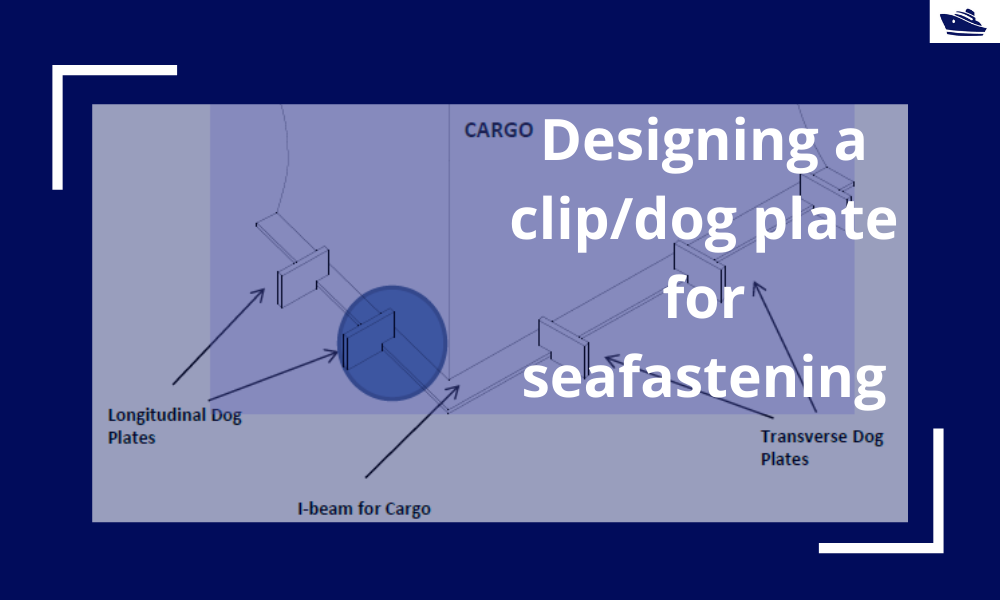
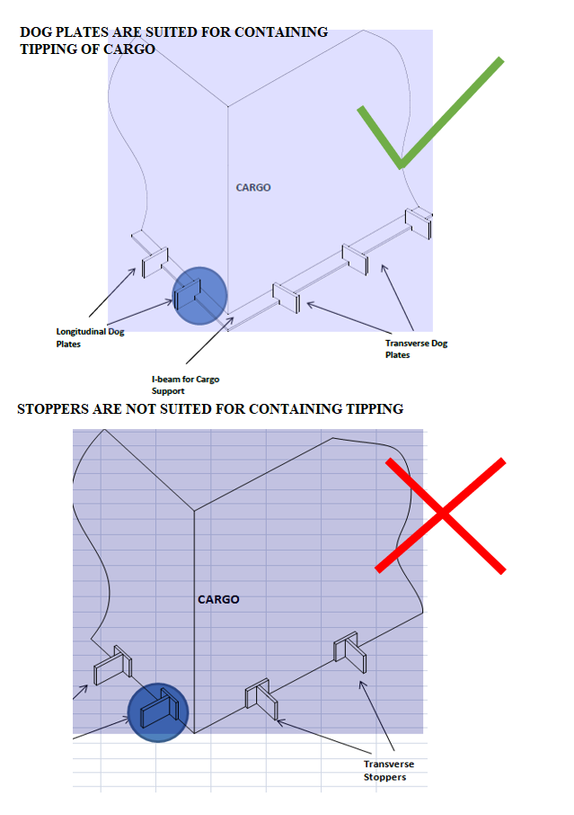
Thinking in basic terms, to prevent cargo from tipping/overturning, we will need something that pins or clips it to the deck. Such a seafastening item is called a ‘Clip’ or a ‘Dog Plate’. Imagining such an item, it can be an ‘L-shaped’ structure that clings on to the base of the cargo. If we see the figure below, the dog plate is like a jaw that clamps down on the base frame of the cargo. We can also see that this kind of structure will help prevent the overturning of the cargo, as compared to stoppers which can prevent only translation. At times, both dog plates and stoppers may be used together on the same cargo with dog plates resisting overturning and stoppers resisting translation.
Designing a Dog Plate:
In this section, we’ll see how do we go about designing a dog plate for a particular operation.
Any design takes up the following flow:
- Evaluate the forces acting on the structure
- Check the stresses on the structure due to the forces
- Iterate the design until the stresses are within the acceptable levels
Forces on the structure:
The cargo on the vessel will experience forces in the three directions – longitudinal, transverse, and vertical (uplift), besides the self-weight of the cargo. The first three forces depend on the environment in which the vessel is operating, and one simple but conservative way of calculating these forces is to follow DNVGL guidelines (See DNVGL-ST-N001, also see our product on Cargo Forces and Accelerations)
Longitudinal or Transverse Forces
In the figure below that shows the plan of a vessel’s deck carrying cargo, we can see that there are multiple dog plates in each direction to resist the respective force (transverse or longitudinal).
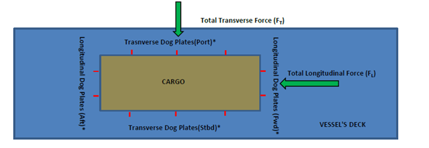
If the number of dog plates in the transverse direction is nT and the total transverse force on the cargo is FT, then the transverse force on a single dog plate in the transverse direction is
FT1 = FT/nT
Similarly, in the longitudinal direction, the total longitudinal force divided by the total number of dog plates in that direction gives the force on one dog plate.
Uplift Force
The uplift force is a vertically upward force due to the cargo motion. It is calculated from a motion analysis or from empirical relations (See our product for Cargo Forces and Accelerations).
Self-Weight of Cargo
The cargo also experiences its own self-weight that acts vertically downwards.
The force diagram of the Cargo can be drawn as below:
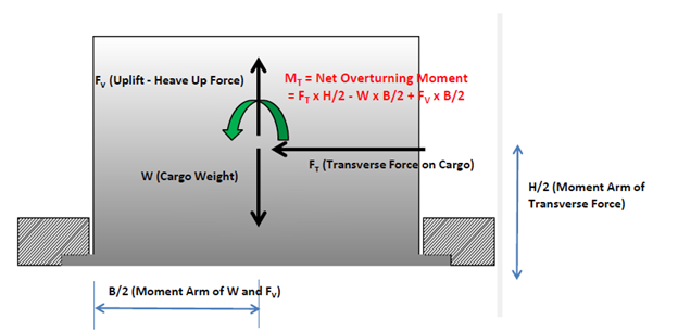
We can see that given the location of the dog plate, the following forces and moments will be experienced by it:
- The transverse force FT will be borne by all the dog plates.
- An overturning moment on the whole cargo, MT, due to FT, Uplift Force, and Self-Weight will also be borne by all dog plates. We can see that while FT and FV will cause the cargo to tip, the restoring moment due to self-weight protects it from tipping.
MT = FT x H/2 – W x B/2 + FV x B/2
The above force and moment can be divided by the number of dog plates (nT in the transverse direction) to give the force and moment per dog plate.
FT1 = FT/nT
MT1 = MT/nT
Translation of forces to the Dog Plate
The net overturning moment MT1 on a single dog plate translates effectively to an uplift force on the dog plate due to the moment. Considering the uplift force to be acting at the dog plates on either side, the effective uplift force on each dog plate is
FV1 = MT1/B
where B is the width of the cargo.
Next, we see the force diagram of the Dog Plate itself:
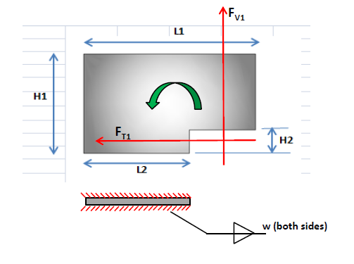
We can see that the following forces are acting on the dog plate:
- The translation force FT1, which gets directly translated from the cargo
- The uplift force FV1, which occurs due to the overturning moment
Stresses on the dog plate
The above two forces lead to various stresses for which the dog plate needs to be analyzed:
- Shear Stress: The force FT1 leads to shear stress on the dog plate
- Tensile stress: The effective tensile force is calculated from the moment of the two forces FT1 and FV1 about the base, divided by the length of the base, L2.
- Bending Stress: bending moment at the base is calculated by adding the bending moments due to FT1 and FV1 at the base.
- Weld Check: The weld of the dog plate to the deck also needs to be checked similarly for shear, tensile and bending stresses
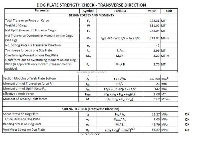
By calculating the forces and moments applicable, the stresses can be calculated, and the suitability of the dog plate evaluated. Some sample calculations are shown below:
Disclaimer: This post is not meant to be authoritative writing on the topic presented. thenavalarch bears no responsibility for the accuracy of this article, or for any incidents/losses arising due to the use of the information in this article in any operation. It is recommended to seek professional advice before executing any activity which draws on information mentioned in this post. All the figures, drawings, and pictures are property of thenavalarch except where indicated, and may not be copied or distributed without permission.
Getting the right thickness of GRP laminate for your boats
Introduction GRP laminates are widely used in the fabrication of high-speed crafts and light crafts/boats globally. GRP stands for Glass Reinforced Plastic. As the name suggests, GRP contains glass fibers embedded into a plastic resin. This gives it higher strength,...
Designing Fillet Welds for Symmetrical Joint Sections
Introduction Fillet welds are the most commonly used weld types in marine structures. A fillet weld is used when there are two pieces of metal that are joined perpendicular to each other or at an angle. In this article, we will explore how to select the right size...
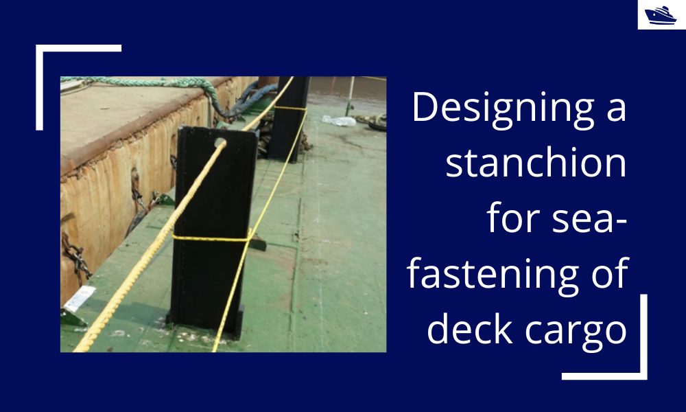
Designing a stanchion/stopper for sea-fastening of deck cargo
Introduction Stanchions – a familiar term for mariners and ship designers. What are Stanchions? A stanchion is generally a vertical pipe or beam which is used to support some structural item or provide support rails on the deck. In ships, the most common type of...
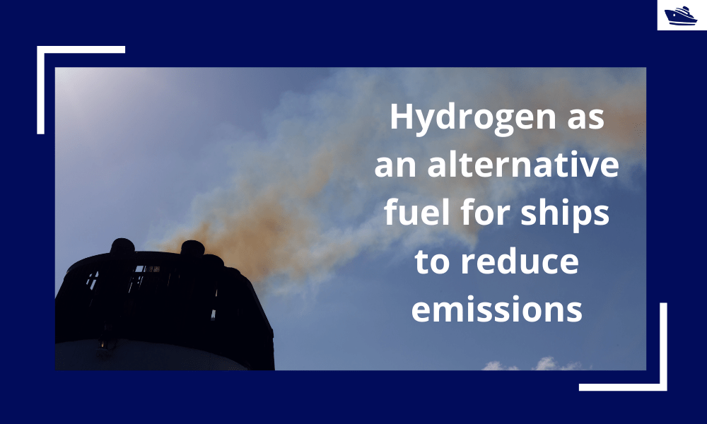
Hydrogen as an alternative fuel for ships to reduce emissions
,This article first appeared in the Feb 2019 edition of Marine Engineers Review. It is being reproduced with minor edits here for the readers of TheNavalArch's blog. Introduction The world is on facing a grave environmental challenge with an increase in carbon...
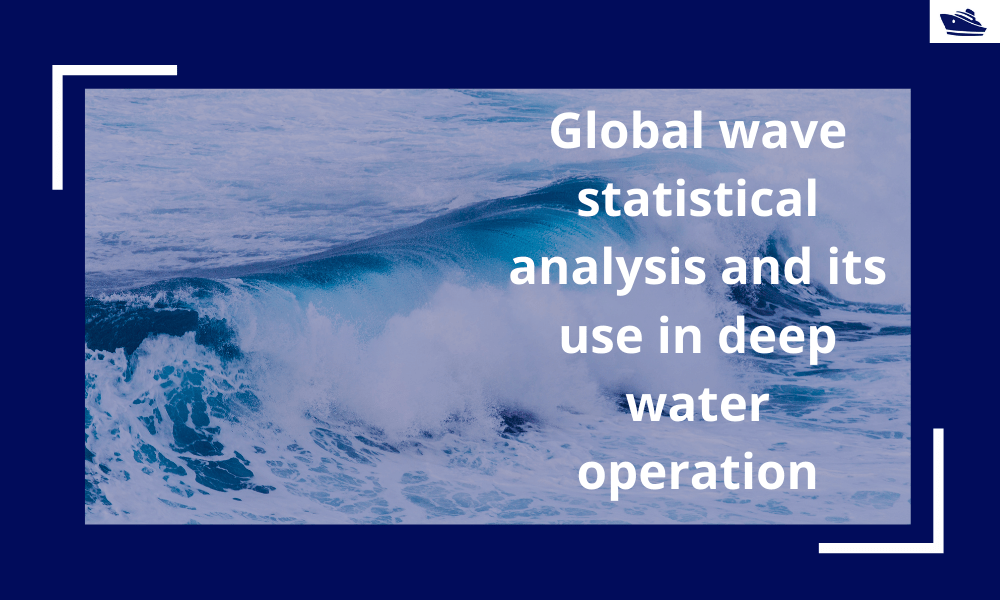
Global wave statistical analysis and its use in deepwater operations
Why do we need wave analysis? For the design of offshore operations such as installation and transport of offshore structures, as well as lifecycle design of floating and fixed structures, knowledge of extreme waves as well as the probability of different sea-states...
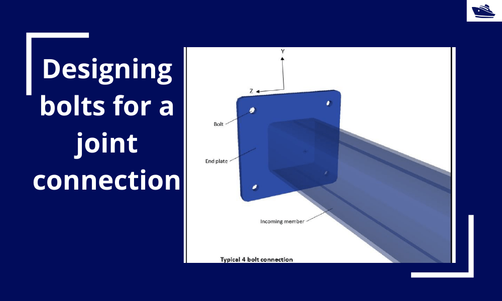
Designing bolts for a joint connection
Introduction Bolts are very commonly used fastening items and used in a variety of configurations. In this article, we will explore in-depth the design of a bolt used in connecting two members at a joint (bolted joint). We'll see what properties of the bolt are...
The why and how of designing a lifting beam
Lifting beams are universally applied gear used widely in various types of lifting operations, onshore and offshore. In this article, we will explore the design of a basic lifting beam and see what design checks are needed to establish the suitability of the beam for...
Draft Surveys: Methodology, Calculations, and common errors
Introduction Marine transport is the backbone of the global trade and reasonably can be considered to be the artery of the global manufacturing supply chain, as more than four fifths of the world merchandise trade by volume is carried by sea. Undoubtfully, the...
The Bulbous Bow – types, characteristics, and effects
This is Part 2 of the two-part series on Bulbous Bows. For Part 1, click here By Tamal Mukherjee, *This article originally appeared in May 2019 edition of Marine Engineers Review (India), the Journal of Institute of Marine Engineers India. It is being...
Marine Propeller and Shafting Alignment – Part 2
Gap & Sag Alignment Gap and Sag Alignment is carried out to bring the engine to its final position, in case of directly coupled installations, and to bring the gear box to its final position in case of installations with reduction boxes. The figure below indicates...

Thanks alot for this brief knowledge
NEED FOR PRINCIPLES OF DESIGNING SEAFASTENINGS