Introduction
In an earlier article, we saw how to design stoppers for seafastening. Stoppers are items that are used to contain the translation movements (longitudinal and transverse directions) of a cargo on the deck/hold of a vessel.
That brings us to the question – what about tipping of the cargo? If the cargo is subjected to external forces that cause it to tip, how do we protect the cargo against tipping?
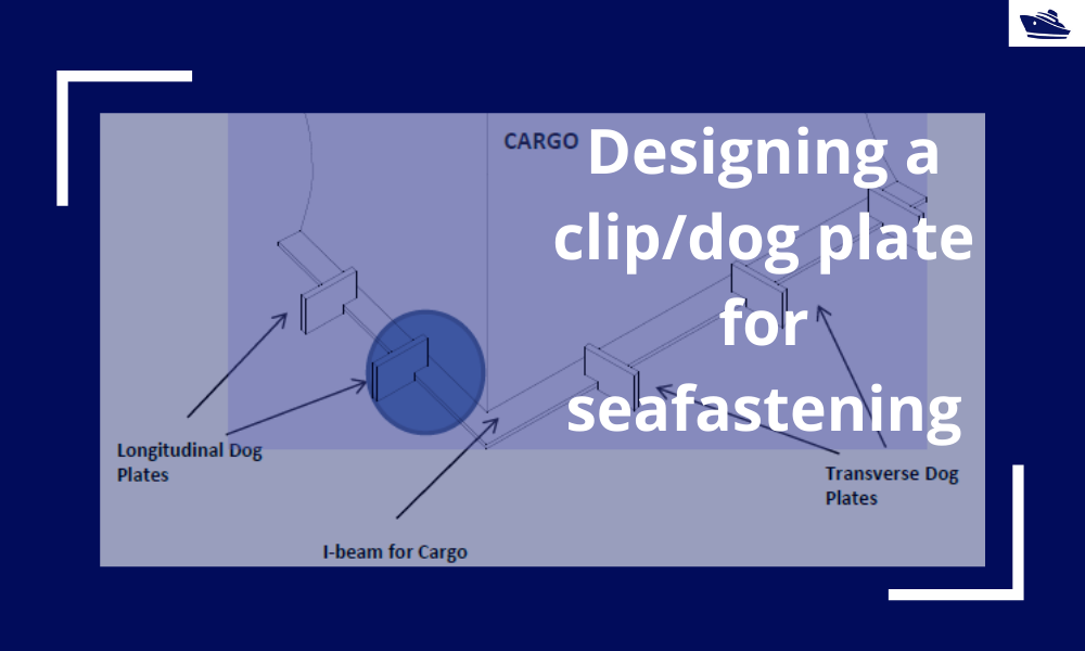
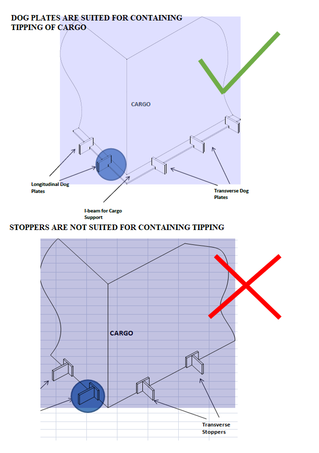
Thinking in basic terms, to prevent cargo from tipping/overturning, we will need something that pins or clips it to the deck. Such a seafastening item is called a ‘Clip’ or a ‘Dog Plate’. Imagining such an item, it can be an ‘L-shaped’ structure that clings on to the base of the cargo. If we see the figure below, the dog plate is like a jaw that clamps down on the base frame of the cargo. We can also see that this kind of structure will help prevent the overturning of the cargo, as compared to stoppers which can prevent only translation. At times, both dog plates and stoppers may be used together on the same cargo with dog plates resisting overturning and stoppers resisting translation.
Designing a Dog Plate:
In this section, we’ll see how do we go about designing a dog plate for a particular operation.
Any design takes up the following flow:
- Evaluate the forces acting on the structure
- Check the stresses on the structure due to the forces
- Iterate the design until the stresses are within the acceptable levels
Forces on the structure:
The cargo on the vessel will experience forces in the three directions – longitudinal, transverse, and vertical (uplift), besides the self-weight of the cargo. The first three forces depend on the environment in which the vessel is operating, and one simple but conservative way of calculating these forces is to follow DNVGL guidelines (See DNVGL-ST-N001, also see our product on Cargo Forces and Accelerations)
Longitudinal or Transverse Forces
In the figure below that shows the plan of a vessel’s deck carrying cargo, we can see that there are multiple dog plates in each direction to resist the respective force (transverse or longitudinal).
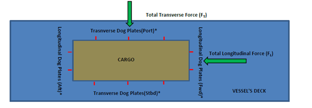
If the number of dog plates in the transverse direction is nT and the total transverse force on the cargo is FT, then the transverse force on a single dog plate in the transverse direction is
FT1 = FT/nT
Similarly, in the longitudinal direction, the total longitudinal force divided by the total number of dog plates in that direction gives the force on one dog plate.
Uplift Force
The uplift force is a vertically upward force due to the cargo motion. It is calculated from a motion analysis or from empirical relations (See our product for Cargo Forces and Accelerations).
Self-Weight of Cargo
The cargo also experiences its own self-weight that acts vertically downwards.
The force diagram of the Cargo can be drawn as below:
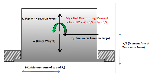
We can see that given the location of the dog plate, the following forces and moments will be experienced by it:
- The transverse force FT will be borne by all the dog plates.
- An overturning moment on the whole cargo, MT, due to FT, Uplift Force, and Self-Weight will also be borne by all dog plates. We can see that while FT and FV will cause the cargo to tip, the restoring moment due to self-weight protects it from tipping.
MT = FT x H/2 – W x B/2 + FV x B/2
The above force and moment can be divided by the number of dog plates (nT in the transverse direction) to give the force and moment per dog plate.
FT1 = FT/nT
MT1 = MT/nT
Translation of forces to the Dog Plate
The net overturning moment MT1 on a single dog plate translates effectively to an uplift force on the dog plate due to the moment. Considering the uplift force to be acting at the dog plates on either side, the effective uplift force on each dog plate is
FV1 = MT1/B
where B is the width of the cargo.
Next, we see the force diagram of the Dog Plate itself:
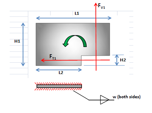
We can see that the following forces are acting on the dog plate:
- The translation force FT1, which gets directly translated from the cargo
- The uplift force FV1, which occurs due to the overturning moment
Stresses on the dog plate
The above two forces lead to various stresses for which the dog plate needs to be analyzed:
- Shear Stress: The force FT1 leads to shear stress on the dog plate
- Tensile stress: The effective tensile force is calculated from the moment of the two forces FT1 and FV1 about the base, divided by the length of the base, L2.
- Bending Stress: bending moment at the base is calculated by adding the bending moments due to FT1 and FV1 at the base.
- Weld Check: The weld of the dog plate to the deck also needs to be checked similarly for shear, tensile and bending stresses
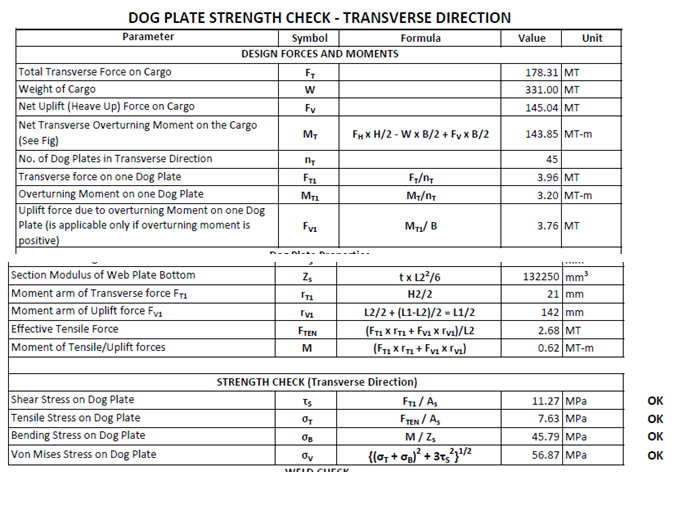
By calculating the forces and moments applicable, the stresses can be calculated, and the suitability of the dog plate evaluated. Some sample calculations are shown below:
Disclaimer: This post is not meant to be authoritative writing on the topic presented. thenavalarch bears no responsibility for the accuracy of this article, or for any incidents/losses arising due to the use of the information in this article in any operation. It is recommended to seek professional advice before executing any activity which draws on information mentioned in this post. All the figures, drawings, and pictures are property of thenavalarch except where indicated, and may not be copied or distributed without permission.
Webcast: Rapid Rigging
Learn a rapid and practical method for generating accurate rigging arrangements and estimating rigging loads in one hour or less using simple engineering principles and streamlined workflows. TECHNICAL WEBCAST OVERVIEWLifting operations can be executed far more...

TheNavalArch’s Interview Series: Peter Farthing (MD, Sensor Technologies)
Peter FarthingManaging Director of Sensor Technologies Ltd and CEO of Advantec Group Limited Interview Introduction TheNavalArch's Interview Series is an endeavor to get insights from the best engineering and business brains in the industry and present them to its...
TheNavalArch Interview Series: Capt Robin Perera
TheNavalArch's Interview Series is an endeavor to get insights from the best engineering and business brains in the industry and present them to its users for the larger benefit of the maritime community. Leaders share their experiences and ideas that readers can gain...
Offshore Installation Vessels Stability Considerations
OFFSHORE INSTALLATION VESSELS STABILITY CONSIDERATIONS By Alan Crowle, BSc, MSc, MScbyRes, CEng, CMarEng, FRINA, FMAREST, FSCMS University of Exeter, College of Engineering, Renewable Energy Group INTRODUCTION The temporary phases of an offshore structure transport...
TheNavalArch Interview Series: Mr Victor Valera
TheNavalArch's Interview Series is an endeavor to get insights from the best engineering and business brains in the industry and present them to its users for the larger benefit of the maritime community. Leaders share their experiences and ideas that readers can gain...
TheNavalArch Interview Series: Mr Steven Lu
Mr. Steven LuManaging DirectorEpoch Offshore Engineering (Shanghai) Co., Ltd. TheNavalArch's Interview Series is an endeavor to get insights from the best engineering and business brains in the industry, and present them to its users for the larger benefit of the...
TRANSPORT VESSELS FOR FLOATING WIND
By Alan Crowle, BSc, MSc, CEng, CMarEng, FRINA, FMAREST, FSCMS Masters by Researcher, University of Exeter, College of Engineering, Mathematics and Physical Sciences, Renewable Energy Group SUMMARY Floating wind turbine construction is a large logistical exercise. The...
TheNavalArch Interview Series: Mr. Balakrishna Menon
Mr. Balakrishna MenonEngineering Director Mooreast (Asia) Pte Ltd TheNavalArch's Interview Series is an endeavor to get insights from the best engineering and business brains in the industry, and present them to its users for the larger...
Floating Rice Fields, the quest for solutions to combat drought floods and rising sea levels
by Lim Soon Heng, BE, PE, FSSS, FIMarEST Founder President, Society of FLOATING SOLUTIONS (Singapore) Abstract Amazing as it seems, there is a case for growing rice on floating platforms in the sea. The capital expenditure to develop this is offset by the opportunity...
CAPSIZE OF LIFTBOAT IN TRANSIT
This paper was originally presented in the 27th Offshore Symposium, February 22nd, 2022, Houston, Texas Texas Section of the Society of Naval Architects and Marine Engineers It has been reproduced here for the readers of TheNavalarch INTRODUCTION In 1989 a Class 105...

Thanks alot for this brief knowledge
NEED FOR PRINCIPLES OF DESIGNING SEAFASTENINGS