This is Part 2 of the two-part series on Bulbous Bows. For Part 1, click here
By Tamal Mukherjee,
*This article originally appeared in May 2019 edition of Marine Engineers Review (India), the Journal of Institute of Marine Engineers India. It is being reproduced here for the readers of TheNavalArch’s blog.
Bulb Forms
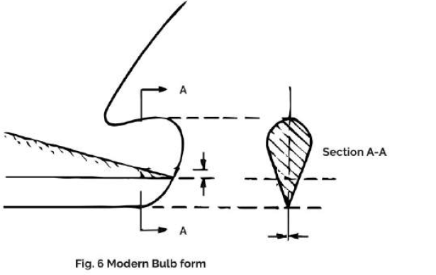
Today bulbous forms tapering sharply underneath are preferred since they reduce slamming. The lower water planes also taper sharply, so that for the vessel in ballast the bulb has the same effect as a normal bow Lengthened(Fig. 6). This avoids additional resistance and sprays formation created by the partially submerged bulb. Bulbs with circular cross-sections are preferred where a simple building procedure is required and the potential danger of slamming effects can be avoided. The optimum relation of the forward section shape to the bulb is usually determined by trial and error in computer simulations.
Modern bulbous forms, wedge-shaped below, and projecting in front of the perpendicular. are geometrically particularly well suited to V section forms. Cylindrical bulbs, projecting forward of the perpendicular, and nonprojecting bulbs can easily be faired into U forward sections. The combinations, suitable in form, Lead also to minimum power requirements.
Bulbous Bow projecting above the Constructed Water Line (CWL)
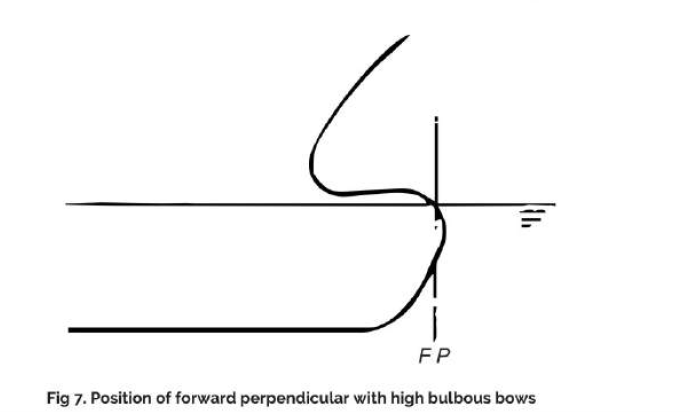
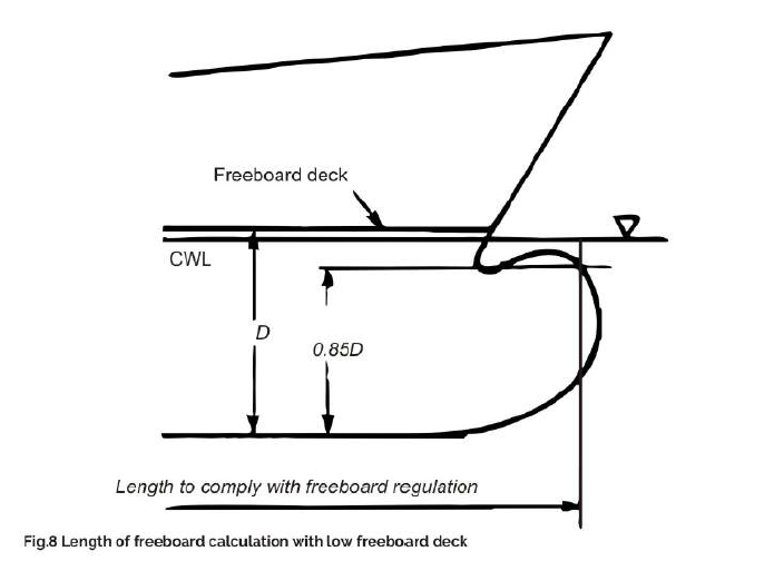
It is often necessary to reduce the resistance caused by the upper side of bulbous bows which project above the CWL creating strong turbulence. The aim should be a fin effect where the upper surface of the bulb runs downwards towards the perpendicular. A bulbous bow projecting above the water line usually has a considerably greater influence on propulsion power requirements than a submerged bulb. Where bulbous bow projects above the CWL, the authorities may stipulate that the forward perpendicular be taken as the point of intersection of the bulb contour with the CWL. Unlike well-submerged bulbs, this type of bulb form can thus increase the calculation length for freeboard and classification (Fig.7). Regarding the bulb height, in applying the freeboard regulations, the Length is measured at 85% of the depth to the freeboard deck. Consequently. even a bulb that only approaches the OWL can still cause an increase in the calculation length of ships with low freeboard decks, e.g. shelter-deckers (Fig. 8).
Projecting Length
The length projecting beyond the forward perpendicular depends on the bulb form and the Froude number. For safety reasons, the bulbous bow is never allowed to project longitudinally beyond the upper end of the stern: 20%is a favorable size for the projection Length. Enlarging this size improves the resistance only negligibly. Today, bulbs are rarely constructed without a projecting length. If the recess in the CWL is filled in, possibly by designing a straight stem line running from the forward edge of the bulb to the upper edge of the stem, the resistance can usually be greatly reduced, This method is however hardly ever used.
Bulb Axis
The bulb axis is not precisely defined. It should slope downwards toward the stern so as to lie in the flow lines. This criterion is also valid for the Line of the maximum bulb breadth and for any concave parts which may be incorporated in the bulb, The inclination of the flow lines directly behind the stem is more pronounced in full than fine vessels. Hence on full ships. the concave part between bulb and hull should incline more steeply towards the stern.
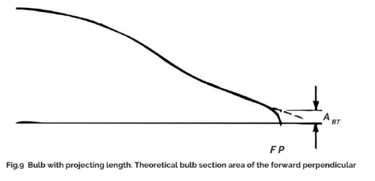
Area Ratio
The area ratio ABT/ AM is the ratio of the bulb area at the forward perpendicular to the midship section area. If the bulb just reaches the forward perpendicular, or the forward edge of the bulb is situated behind the forward perpendicular the lines are faired by plotting against the curvature of the section area curve to the perpendicular (Fig. 9). At the design draught, the resistance of the ship with deeply submerged bulb decreases with increasing area ratio. A reduction of the area ratio (well below the resistance optimum) can, however, be advocated in the light of the following aspects:
- Low resistance at ballast draught.
- Avoidance of excessive slamming effects.
- The ability to perform anchoring operations without the anchor touching the bulb.
- Too great a width may increase the resistance of high bulbs since these are particularly exposed to turbulence in the upper area.
The effective area ratio can be further increased if the bulb is allowed to project above the CWL. Although the section above the CWL is not included in the normal evaluation of the area ratio, it increases the effective area ratio and can considerably reduce resistance, provided that the bulb is of suitable shape.
Transition
The transition from a bulbous bow to the hull can be either faired or be discontinuous (superimposed bulb). The faired-in form usually has lower resistance. The more the hollow surface ties in the flow lines, the less it increases resistance.
Bases for comparison between Bulbous and Normal Bows
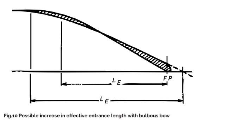
In the normal bow/bulbous bow comparison, alternative consideration and comparative model experiments usually assume a constant water plane length between the perpendiculars. The conventional methods to calculate the resistance of a modern vessel with bulbous bow start with a bulb-less ship and then adjust to the resistance. This resistance deduction is made in only a few of the resistance calculation methods, usually insufficiently and without taking into account those bulbs with pronounced projecting forms. The reduction in resistance can relate to the form resistance or to the overall resistance. In view of the widely differing hydrodynamic lengths of basis ships with and without bulbous bows, estimates of savings on power due to the bulbous bow are considerably less reliable than for earlier bulbous forms, which only extended to the forward perpendicular. The bulb may reduce resistance in the range of 0.175 <= Fn <= 0.7. Earlier non-projecting bulbs decreased resistance at best by some 6%. Modern bulbs decrease resistance often by more than 20%. Whereas above Fn = 0.23 the main effect of the bulb is to shift the bow wave forward, the voluminous bulbs and relatively short wavelengths of slower vessels may also cause displacement to shift forward from the area of the forward shoulder. In this way, the bulb displacement can be used to position the forward shoulder further aft, so that the entrance length approximates to the wavelength (Fig. 10). Another way to decrease resistance is to reduce trim at the stern.
Effects of Bulbous Bows on Ship’s Characteristics
The effects of a bulbous bow can extend to several areas of the ship’s design, construction, manufacture, and operation, as in the following :
- Effective drag (total resistance) and characteristics at various draughts.
- Resistance in a seaway.
- Seakeeping characteristics.
- Propulsion characteristics.
- Course-keeping ability and maneuverability
- Bow-thruster
- Possibilities for installation. (ID) Efficiency.
- Additional resistance
- Trim
- Construction. manufacture and building costs of the bow section
- Freeboard.
- Anchor-handling apparatus and operation with respect to the danger of anchor striking bulbous bow.
- Accommodation of sounding devices on fishing and research vessels.
- Observing length restrictions due to docks and locks.
- Ice operation.
Of the above characteristics, the details of the three important characteristics are as follows :
1. Ice operation with bulbous bow
A certain ice-breaking capability can be achieved if the position of the upper side of the bulb enables it to raise an ice sheet. For operation in medium-thick ice, the bulbous bow has greater advantages than conventional, and even icebreaking bows because it turns the broken lumps so that their wet sides slide along the hull, thus causing less wear on the outer shell and less resistance. The maximum thickness which a bulbous bow can break is less than for special ice-breaking bow forms.
2. Seakeeping characteristics with bulbous bow
Three characteristics are of interest here:
- Damping of pitching motion: Generally speaking, bulbous bows increase pitch motion damping, especially when designed for the purpose. The damping is particularly pronounced in the area of resonance when the wavelength roughly corresponds to the ship’s length. There is even some damping for shorter wavelengths. For wavelengths exceeding 1.-1.5 ship’s lengths, ships with bulbous bows will experience an increase in pitch amplitude. However, the pitch amplitude in this range is small in relation to the wave height.
- The ability to operate without reduction of power even in heavier seas. Sharp-keeled bulbs can withstand slamming effects in more severe seas than normal bulbs. Where the bulbous bow has a flat upper surface, water striking the bow may cause pounding.
- The increased power requirements in waves. Bulbous bows increase the added resistance due to waves, despite the smoother operation in heavy seas. This is analogous to the effect of the bilge keel. The energy of damping has to be taken from the propulsive power. For wavelengths shorter than o.9x the ship’s length the pitching frequency of the ship is subcritical. Then the bulb may reduce the added resistance.
3. Power requirements with bulbous bow
The change in power requirement with the bulbous bow, as opposed to the ‘normal’ bow, can be attributed to the following:
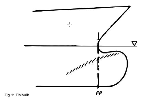
- Change in the pressure drag due to the displacing effect of the bulb and the fin effect. The bulb has an upper part which acts like a fin (Fig. 11). This fin-action is used by the ‘ stream-flow bulb’ to give the sternward flow a downward component, thus diminishing the bow wave. Where the upper side of the bulb rises towards the stem, however, the fin effect decreases this resistance advantage. Since a fin effect can hardly be avoided, care should be taken that the effect works in the right direction. Surprisingly little use is made of this resistance reduction method.
- Change in wave breaking with or without bulb: spray can form at the bow. By shaping the bow suitably (e.g. with sharply tapering waterlines and steep sections), spray can be reduced or completely eliminated
- Increase in frictional resistance. The increased area of the wetted surface increases the frictional resistance At low speeds. this increase is usually greater than the reduction in resistance caused by other factors.
- Change in the energy of the vortices originating at the bow. A vortex is created because the lateral acceleration of the water in the CWL area of the forebody is greater than it is below. The separation of vortices is sometimes seen at the bilge in the area of the forward The bulbous bow can be used to change these vortices. This may reduce energy losses due to these vortices and affect also the degree of energy recovery by the propeller.
- Change in propulsion efficiency influenced by (a) Thrust loading coefficient (b) Uniformity of flow velocity.
In comparative experiments on models with and without bulbous bows, those with bulbous bows show usually better propulsion characteristics. The obvious explanation that because the resistance is lower, a lower thrust coefficient is also effective, which leads to higher propeller efficiency in cargo ships, is correct but not sufficient. Even at speeds where the resistances are equal and the propeller thrust loading coefficients roughly similar, there is usually an improvement of several percent in the bulbous bow alternative. One explanation of why the bulb improves propulsion efficiency comes from comparative experiments, where it was determined that greater effective wake is produced in ships with bulbous bows. The same conclusion is obtained by numerical simulations for tanker hull forms. The power savings by a bulbous bow may, depending on the shape of the bulb, increase or decrease with a reduction in the draught. The lower sections of modern bulbous bows often taper sharply. The advantage of these bulbous bows is particularly noticeable for the ship in ballast.
Criteria for the practical application of Bulbous Bows
Writers on the subject deal with the bulbous bow almost exclusively from the hydrodynamic point of view, ignoring overall economic considerations. The power savings of a bulbous bow should be considered in conjunction with the variability of the draught and sea conditions. Capital expenditure should also be taken into account. The total costs would then be compared with those for an equivalent ship without a bulbous bow. Selection methods such as these do not yet exist. The following approach can be used in a more detailed study of the appropriate areas of application of bulbous bows. Most of the procedures used to determine a ship’s resistance are based on forms without a bulbous bow. Some allow for the old type of bulbous bow where the bulb was well submerged and did not project beyond the perpendicular. A comparison between ships with and without bulbous bow usually assumes waterlines of equal length, as is the case when considering alternatives or conducting comparative experiments with models, The usual method of calculating the resistance of a modern ship with a bulbous bow into take a ship without a bulb and then make a correction to the resistance.
Some methods include this correction, others rely on collecting external data to perform the correction. The change in a ship’s resistance caused by the bulbous bow depends both on the form and size of the bulb and on the form and speed of the ship.
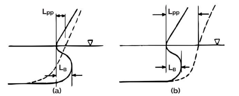
One way of ascertaining the effect of modern bulbs on the resistance is to use a ‘power-equivalent length’ in the calculation instead of LPP (length between perpendiculars) or LWL (length of water line). The ‘equivalent length’ is the length of a bulb-less ship of the same displacement with the same smooth-water resistance as the ship with a bulb. The equivalent length is a function of bulb form, bulb size, Froude number, and block coefficient. If bulb forms are assumed to be particularly good and the bulb is of normal size to ensure compatibility with the other desired characteristics, the resulting equivalent length will range from being only slightly greater than LPP for small Froude numbers to LPP plus three bulb Lengths for Fn>o 3. The equivalent Length of conventional cargo ships with Froude numbers below Fn = 0.26 is shorter than the hydrodynamic length, i.e. shorter than LPP increased by the projecting part of the bulb, i.e. LB or bulb length. (Fig.12)
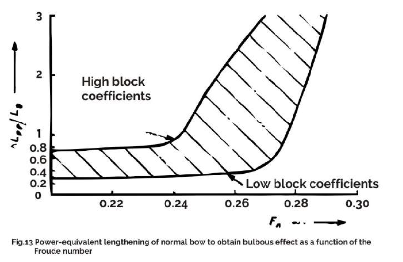
For 0.29<Fn<0.32, lengthening the CWL of smaller ships reduces the power more than a bulbous bow corresponding to the CWL lengthening. However, a bulbous bow installed on ships with Fn>o.26 reduces power more than lengthening the water plane by the projecting length of the bulb.
Fig.13 shows how far a normal bow (without bulb) must be lengthened by deltaLPP to save the same amount of power as a bulbous bow, where LB is the length of the bulb which projects beyond the perpendicular and deltaLPP is the power-equivalent lengthening of the normal form. On the upper boundary of the shaded area are located ships that have a high or too high CB (block coefficient) in relation to Fn and vice versa. For Fn < 0.24 the equivalent increase in length is always less than the length of the bulbous bow. For Fn > 0.3, the bulb effect may not be achieved by lengthening. Thus determining an equivalent length is useful when deciding whether or not a bulbous bow is sensible.
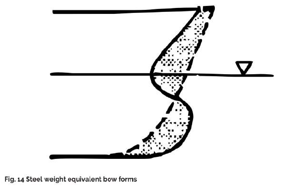
Steel Equivalent Length
This is the Length of a ship without a bulbous bow which produces the same hull steel weight as the ship of equal displacement with a bulbous bow (Fig. 14).
Conclusions of the Equivalent Lengths Study
The problem of finding an ‘optimal’ Length can be simplified by taking only the main factors into account and comparing only a few of the possible alternatives. Considerations can be restricted by making only the normal contractual conditions the basis of these considerations. Seakeeping and partial loading can then be disregarded for the time being. The normal procedure, in this case, is to compare a ship without a bulb with the same ship with a bulb and to determine the decrease in propulsion power, More appropriate are comparisons of cost-equivalent or power-equivalent forms. Here. the following distinctions are made:
- The ship is designed as a full-decker, so attention must be paid to the freeboard
- The ship is not governed by freeboard considerations within the range implied by a small increase in length
The freeboard is a Limiting factor for full-deckers. The vessel cannot simply be built with a lengthened normal fore body instead of a bulbous bow without increasing the freeboard and reducing the draught. If the freeboard is not limiting, there is greater freedom in optimization:
- A proposed bulbous bow ship can be compared with a ship with a normal bow and the normal bow lengthened until power equivalence is achieved. This shows immediately which alternative is more costly in terms of steel. All other cost components remain unchanged.
- The propulsion power can be compared to that for a normal bow with the equivalent amount of steel.
In both cases the differences in production costs and in the ship’s characteristics can be estimated with reasonable precision, thus providing a basis for choice.
Throughout, only ships with bulbs projecting forward of the perpendicular and ships with normal bulb-less bows have been compared. If a comparative study produces an equivalence of production costs or power, then the ship without bulbs will suffer smaller operational losses in a seaway (depending on the type of bulb used in the comparative design) and possess better partial loading characteristics. A more extensive study would also examine non-projecting bulbous bows. The savings in power resulting from these can be estimated more precisely. and are within a narrower range.
CONCLUSION
In summary, it can be said that there is hardly any disadvantage of using a bulbous bow, however, a few factors must be always kept in mind before installing one, that is, a bulb is only useful for long voyage ships, especially. Merchant Vessels as it operates only for a given range of speed.
ABOUT AUTHOR:
Tamal Mukherjee has sailed as a Chief Engineer on ocean-going vessels and thereafter worked with GESCO as a Senior Manager looking after their fleet.
He has been a surveyor with GL and presently director of Fidere Marine Services. He is a visiting faculty for the Neotia University at Kolkata.
Disclaimer:
The views, information, or opinions expressed in this article are solely those of the author and do not necessarily represent those of TheNavalArch Pte Ltd and its employees
Webcast: Rapid Rigging
Learn a rapid and practical method for generating accurate rigging arrangements and estimating rigging loads in one hour or less using simple engineering principles and streamlined workflows. TECHNICAL WEBCAST OVERVIEWLifting operations can be executed far more...

TheNavalArch’s Interview Series: Peter Farthing (MD, Sensor Technologies)
Peter FarthingManaging Director of Sensor Technologies Ltd and CEO of Advantec Group Limited Interview Introduction TheNavalArch's Interview Series is an endeavor to get insights from the best engineering and business brains in the industry and present them to its...
TheNavalArch Interview Series: Capt Robin Perera
TheNavalArch's Interview Series is an endeavor to get insights from the best engineering and business brains in the industry and present them to its users for the larger benefit of the maritime community. Leaders share their experiences and ideas that readers can gain...
Offshore Installation Vessels Stability Considerations
OFFSHORE INSTALLATION VESSELS STABILITY CONSIDERATIONS By Alan Crowle, BSc, MSc, MScbyRes, CEng, CMarEng, FRINA, FMAREST, FSCMS University of Exeter, College of Engineering, Renewable Energy Group INTRODUCTION The temporary phases of an offshore structure transport...
TheNavalArch Interview Series: Mr Victor Valera
TheNavalArch's Interview Series is an endeavor to get insights from the best engineering and business brains in the industry and present them to its users for the larger benefit of the maritime community. Leaders share their experiences and ideas that readers can gain...
TheNavalArch Interview Series: Mr Steven Lu
Mr. Steven LuManaging DirectorEpoch Offshore Engineering (Shanghai) Co., Ltd. TheNavalArch's Interview Series is an endeavor to get insights from the best engineering and business brains in the industry, and present them to its users for the larger benefit of the...
TRANSPORT VESSELS FOR FLOATING WIND
By Alan Crowle, BSc, MSc, CEng, CMarEng, FRINA, FMAREST, FSCMS Masters by Researcher, University of Exeter, College of Engineering, Mathematics and Physical Sciences, Renewable Energy Group SUMMARY Floating wind turbine construction is a large logistical exercise. The...
TheNavalArch Interview Series: Mr. Balakrishna Menon
Mr. Balakrishna MenonEngineering Director Mooreast (Asia) Pte Ltd TheNavalArch's Interview Series is an endeavor to get insights from the best engineering and business brains in the industry, and present them to its users for the larger...
Floating Rice Fields, the quest for solutions to combat drought floods and rising sea levels
by Lim Soon Heng, BE, PE, FSSS, FIMarEST Founder President, Society of FLOATING SOLUTIONS (Singapore) Abstract Amazing as it seems, there is a case for growing rice on floating platforms in the sea. The capital expenditure to develop this is offset by the opportunity...
CAPSIZE OF LIFTBOAT IN TRANSIT
This paper was originally presented in the 27th Offshore Symposium, February 22nd, 2022, Houston, Texas Texas Section of the Society of Naval Architects and Marine Engineers It has been reproduced here for the readers of TheNavalarch INTRODUCTION In 1989 a Class 105...

Very interesting article.
Thanks Alexander
I seen a bolbous bow with 0.28 written in it. I know it stands for its length but what unit of measurement is that ?
Considering fuel costs appear to be on an ever upward trajectory, is there any consideration of developing a dynamic nose geometry that can change shape as a function of speed to maximize efficiency analogous to sweep wing supersonic aircraft?
No comment
Nice aticle
This article is really worth for enrichment may knowledge
Thanks for your kind words Eko. Please keep visiting