Spreader beams are universally applied gear which is widely used in various types of lifting operations, onshore and offshore. In this article, we will explore the design of a basic spreader beam and see what design checks are needed to establish the suitability of a spreader beam for particular lifting operation.
The spreader beam discussed here is one with two lifting points, from which the lifting slings go vertically straight down to the lashing points on the cargo as shown in the figure below:
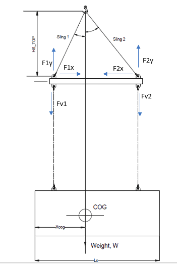
Fig 1: Arrangement of a spreader bar
Spreader beam vs Lifting beam
At the outset, it is important to clarify the difference between a spreader and a lifting beam. A spreader beam is designed to take primarily compressive loads, as can be seen in the figure above.
If we resolve the forces on the whole beam, we get the force diagram as above. We can see that the vertical downward forces of Fv1 and Fv2 are balanced by the components F1y and F2y, while F1x and F2x are the compressive forces on the spreader. Some bending may be experienced as the forces F1x and F2x are acting at the hole of the pad-eye, which is offset from the centerline of the spreader by some distance. However, the primary load on the spreader is compressive stress. There can be some lateral-torsional buckling too if it is an I-beam spreader.
Lifting beams, on the other hand, are designed to take bending loads. A simple lifting beam is shown below:
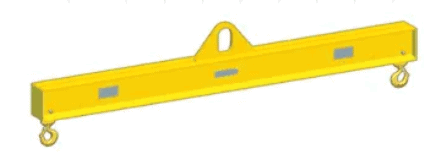
Fig 2: A simple lifting beam
We can see that it has a lifting eye at its top in the middle, while the eyes below are used to connect the slings to the lifted object. If we resolve the forces, we can immediately see that the lifting beam will be primarily under bending stress (see figure below).
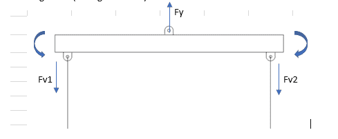
Fig 3: Forces and moments on lifting beam
Loads on the Spreader Beam
Next, we analyze the loads which affect the spreader’s design.
Following are the loads which affect the spreader:
- Lifted object weight and CoG – the lifted object’s weight is to be borne by the spreader beam. Further, the location of the CoG of the lifted object has critical effect on the sling loads. If the CoG is not located at mid-point of the cargo (lengthwise, see Fig 1), then the loads on the slings will not be the same. The sling which is closer to the CoG is expected to take more load
- Rigging Weight – additionally, the rigging weight below the spreader is to be added
- Dynamic Amplification factor – depending on the environment of the lifting (onshore or offshore), a Dynamic Amplification Factor is to be added to the load. This can be found in DNVGL-ST-N001 (2016), 16.2.5.6
Sling Angles and Loads
The angles of the slings 1 & 2 (in figure 1) made with the vertical must be less than 45 degrees (16.3.4.2, DNVGL-ST-N001). It is to be noted that the center of gravity (COG) of the lifted object has to be in line (on the same vertical) as the crane hook. The sling lengths are to be accordingly adjusted. If not, the object will experience a tilt during lifting which is not desirable.
The next step is to calculate the loads on the slings above the spreader, i.e., the line tensions in the slings 1 & 2. The Dynamic Hook Load (DHL) is determined for this and using a simple mathematical formulation, the sling loads are determined. It is expected that the lift point which is closer to the COG will take more load.
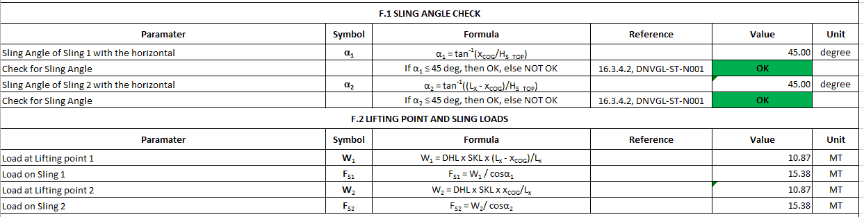
Fig 4: Sling angle and sling loads
Stresses
The next step is the calculation of stresses. The spreader experiences the following stresses:
- Compressive Stress – this is the governing stress of the spreader. This is calculated by dividing the compressive force on the spreader by the section area of the spreader. The allowable compressive stress is calculated in accordance with AISC ASD, Sec E2 by calculating the slenderness ratio (KL/r) of the spreader, and the factor Cc which depends on the material properties of the spreader.
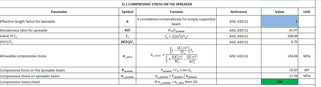
Fig 5: Compressive stress check
- Bending Stress – the bending of the spreader is caused by the force on the pad-eye acting at a vertical offset between the eye of lifting lug and the longitudinal axis of the spreader (see hp in the figure below). Bending is also caused due to the self-weight of the spreader. Together, these moments divided by the section modulus of the spreader give the bending stress. The allowable bending stress is obtained from the AISC ASD
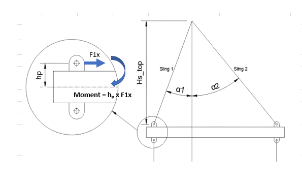 Fig 6: Bending moment due to offset of force from centerline
- Shear Stress – the vertical loads on the lifting points cause shear stress. Dividing these loads by the section area of the spreader gives the shear stress
- Combined Stress check – a combined axial compression and bending check is also required for the spreader as per AISS ASD H1
- Lateral torsional buckling – if the spreader section is I-beam, then a lateral-torsional buckling possibility needs to be investigated, depending on whether the flange/web is compact/non-compact. This is done as per AISC ASD Sec F2.
With all the above checks performed, a complete design assessment of a spreader for a specific lifting operation can be done. Spreaders can come in different section shapes, the most common being I-beam, hollow circular, and hollow rectangular.
TheNavalArch has its own app for spreader beam design which performs all the checks diligently and can be used to either design a new spreader or check the suitability of an existing one for any lifting operation. Please do spend some time exploring it through the link below.
Disclaimer: This post is not meant to be authoritative writing on the topic presented. thenavalarch bears no responsibility for the accuracy of this article, or for any incidents/losses arising due to the use of the information in this article in any operation. It is recommended to seek professional advice before executing any activity which draws on information mentioned in this post. All the figures, drawings, and pictures are property of thenavalarch except where indicated, and may not be copied or distributed without permission.
Why the bollard pull calculation method for a barge won’t work for a ship
In my working with the marine transportation industry for more than a decade now, I have come across many different calculations for required bollard pull for both barges and ships. The principles of the calculation are same, whether it is a ship, a barge...
STEEL COILS LOADING – ITS CHALLENGES AND WAYS TO OVERCOME
STEEL COILS LOADING – ITS CHALLENGES AND WAYS TO OVERCOME by Mr. Spiros Malliaroudakis (Founder & Managing Director, S.A. Malliaroudakis Maritime (UK) Ltd) The loads derived from steel coils loading are very concentrated, leading to higher stresses...
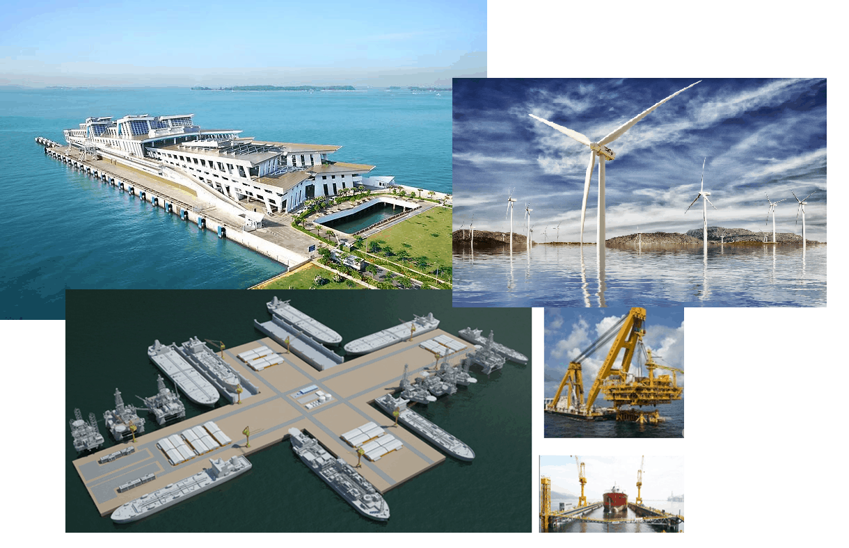
Naval architecture, new challenges and a new horizon
Naval architecture, new challenges and a new horizon by Lim Soon Heng, BE, PE, FSSS, FIMarEST Founder President, Society of FLOATING SOLUTIONS (Singapore) Civilization has arrived at a point of inflexion triggered by global warming and rising sea levels....
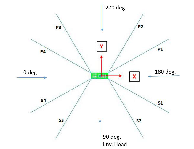
Mooring System Design and Analysis
Mooring System Design and Analysis by Rahul Kanotra, Consultant Naval Architect As the offshore industry moves towards greater technological advancements, one thing that has plagued the engineers is the “plug and play” computer programs or software. I am not against...
Cargo Stoppers – why they are critical and how to design them
Stoppers and their critical role in seafastening of cargo Introduction A cargo transported on the deck of a ship is subject to many forces. These forces comprise of the inertial forces due to the ship motions – the three translations and three rotations – and the...
Are you chartering a tug bigger than necessary for your Barge?
Barges are one of the most frequently used means for transporting deck cargo of different shape, size and weight. While some barges are self-propelled, the majority is towed by another vessel called a ‘Tug’. Once an owner or charterer...
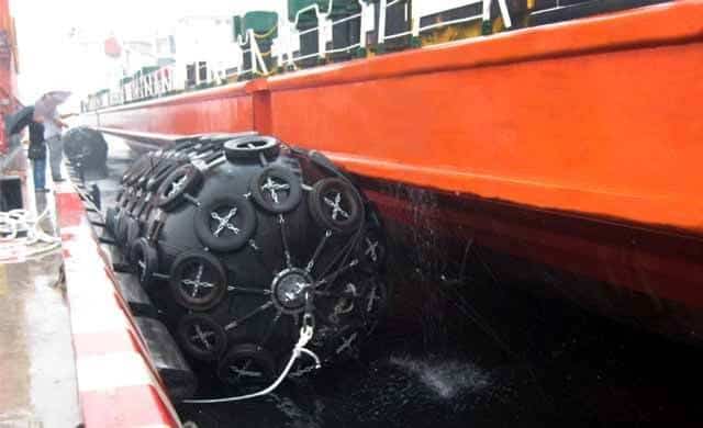
Fendering – an Introduction
In this two part article we will talk about Fendering, which is one of the basic but critical operations related to a ship. Fendering is, basically, protecting the ship’s sides from contact with another body (which can be another ship, jetty or quay wall). It can also...
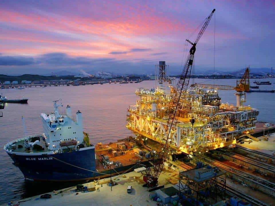
Loadouts – An introduction
Image source: Flickr Loadout Operations - an Introduction Loadout is a term oft heard of in the marine/offshore industry parlance. Loadout is generally referred to the operation of transferring a Cargo or a Structure from the place of fabrication to a sea-borne...
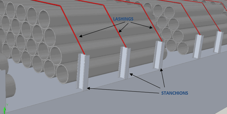
Introduction to Pipe Transportation – Part 3 (Engineering)
Introduction to Pipe Transportation - EngineeringIn Part 1 we learnt about pipes, while in Part 2 we learnt about Planning and Scheduling of pipe transport operations. In this part, we will learn about Engineering.Phase 3 – Engineering.Engineering for pipe...
Introduction to Pipe Transportation – Part 2 (Planning & Scheduling)
In Part 1, we looked at the properties of pipes. In this section, we will be looking at the Planning & Scheduling of a pipe transportation operation (see below, Phase 1 & 2) SECTION 2: PLANNING, SCHEDULING, AND ENGINEERING FOR A PIPE TRANSPORT PROJECT Source:...

At first, I’m fan club your product for lifting lug. I read this article, it is very well explanation.
By the way, in the paragraph of sling angles and loads, you mention that
“The angles of the sling 1 & 2 (in figure 1) made with the horizontal must be less than 45 degree”
It seem to be not correct. Your figure is show angle made with vertical.
Dear Weerawut
Many thanks for your feedback. Yes, the article did have a mistake, it should be the angle made with the vertical. We’ve corrected the same.
Thanks for highlighting this
Team TheNavalArch
Thanks for sharing such helpful posts! We work for the same cause!
Good morning, I am about to download your lifting beam spreadsheet, however, would like to ash a question in relation to the use of spreader beam with top lift slings supporting beam and main lift slings are attached to hook extend down past beam to the load. Load to be lifted (a column) is 200t in weight COG is central and towards base.
The slings connect directly to lifting trunnions. How do you calculate what load is being transmitted to the spreader top support slings when actual load is being carried by main slings. Spreader bar ends to be greased to reduce friction, sling angle for main slings 30 degrees (included angle 60 deg). The reason for this is crane capacity and required boom length required negates the use of additional shackles for normal spreader configuration. (Reduced head room).
very interesting and straight-forward article, thanks for sharing …. correct me if i am wrong but looking to the sketch (fig. 1) i guess that there is a inaccuracy in the evaluation of tan a1. Xcog should not be the distance between the cargo COG and its edge but should be the distance between COG and the vertical projection of the suspension point “1” in the final equilibrium configuration. or at least the item to be taken in consideration in a1 definition should be Xcog minus the distance on the vertical plane between the suspension point and the edge of the cargo if the first is unknown ….
Hi, Thanks for the detailed explanation. Can we know how about using the top two slings of the spreader beam in vertical for two hooks/tandem lift? I assume the bottom and top forces will be neutral and hence can be used, as the SB is already suitable for compressive forces. Please provide your insight.
In the calc of the compressive forces it’s only accounting Fs1, one force in the extremities, however for this case I suppose to calculate the resultant force in the two extremities, as these forces can be differents.