Introduction
Stanchions – a familiar term for mariners and ship designers. What are Stanchions?
A stanchion is generally a vertical pipe or beam which is used to support some structural item or provide support rails on the deck. In ships, the most common type of stanchion is support rails at the edge of the deck for people onboard to lean on to prevent falling over. It can also be used to support lifesaving appliances like lifebuoys/liferafts etc, and many times reinforced to support heavier structures.

Stanchions for hand rails
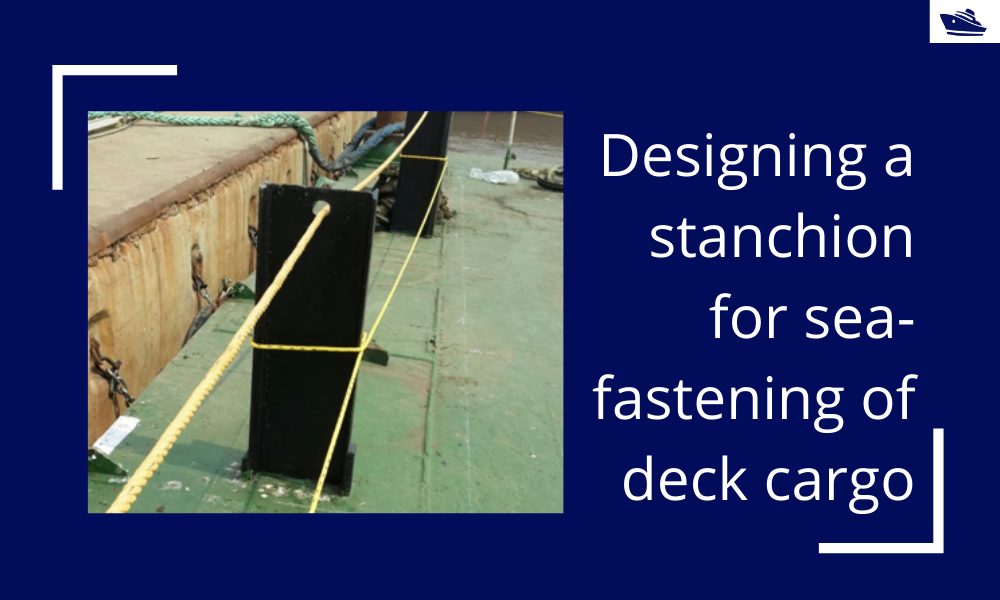
Stanchion/Stopper for seafastening
For seafastening of cargo, the stanchion needs to be designed to take the loads on the cargo during seafastening. Basically, the stanchion/stopper is placed at the sides and ends of the cargo to prevent the cargo’s sliding in the transverse and longitudinal directions respectively. This can be seen in the figure below:
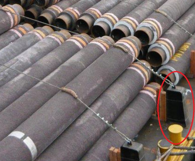
Stanchion used to support pipes on deck
Interchangeably, these stanchions are also called stoppers. However, the stopper is a more generic term and is used to cover other geometries too. For a comprehensive article on stoppers, please check out this article on stoppers.
The most common stanchion used is the H-beam stanchion due to its simplicity. Pipe stanchions may also be used in some cases.
In this article, we will look into the design of an H-beam) stanchion and the various stresses that govern its strength.
These principles can be used to assess existing stanchions on the deck of a vessel for their suitability for use with a given cargo too.
A simple H-beam stanchion drawing is shown below:
In some cases, such a stanchion may be further reinforced at on one side to take greater loads, as shown below:
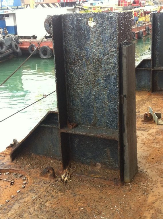
Stanchion with reinforcement at back face
Loads
The cargo load on the stanchion can be of two types:
- A point load – the stanchion can take a point load if the cargo if fastened to the stanchion using a lashing. In this case, the stanchion generally has an in-built lashing eye, or an external pad-eye can be welded to it (generally at the top) to create the fastening point.
- Distributed load – a stanchion takes distributed load when the cargo is resting against it, and full or partial face of the stanchion takes the load.

Stanchion with Distributed Load
Stanchion with point load at the top
Stress Check
In this section, we’ll see for the two cases of loading, the applicable stresses, and how to go about calculating them.
Case 1 – Distributed Load
When the cargo is resting against the face of the stanchion, the total load and stresses on the stanchion can be calculated by the following method:
- Calculate the transverse/longitudinal force on the cargo. The transverse/longitudinal force on the cargo can be calculated using an analysis, or using empirical relations (check out our product Cargo Forces and Accelerations)
- Divide the total transverse or longitudinal force by the number of stanchions in the respective direction. For example, if the total transverse force on the cargo is 100 MT and there are 4 stanchions supporting it, the load on one stanchion in 25 MT
- Calculate the design load per unit length by dividing the load on the stanchion by the total height of the stanchion which takes the distributed load. It is to be noted that not the entire face of the stanchion may take the load, and only the part which takes the load should be taken into account for calculations.
- Calculate the design moment on the stanchion due to the distributed load
- Calculate the section properties of the H-beam section of the stanchion. This includes shear/tensile areas and section moduli about the two axes.
- The stanchion is not subject to axial stress due to no load being in the axial direction.
- The shear stress is calculated by dividing the total transverse/longitudinal load by the shear area
- The bending stress is calculated by dividing the total transverse/longitudinal moment by its respective section modulus.
- Weld Check – it is important to perform strength check for the weld that secures the stanchion to the deck. Similar to the stanchion, shear and bending moment checks need to be performed for the weld too by calculating its shear area and section moduli.
Case 2 – Point Load
When the load on the stanchion is a point load, the steps of calculation still remain the same as for the distributed load, except for the following changes:
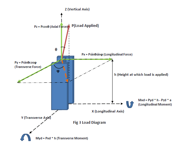
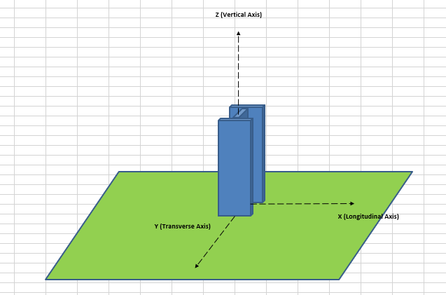
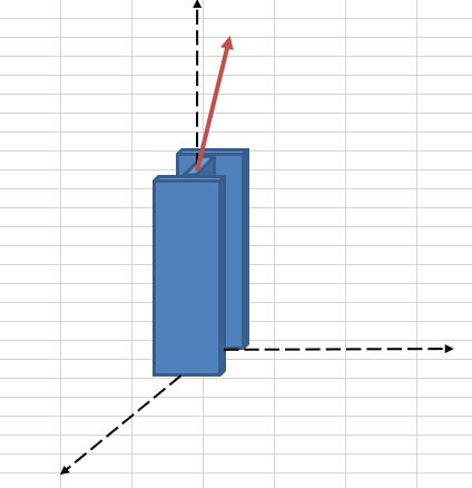
Stanchion with point load – force resolution
- The load on an individual stanchion is the load on the lashing between cargo and the stanchion. This load comes from seafastening calculation
- The load on the stanchion will resolve to loads along the three axes of the stanchion as shown below
These loads will also lead to design moments about both X and Y axes as shown above.
- The stanchion will experience a tensile force as well due to the axial component of the design load
- Out-of-plane bending stresses also need to be checked (for moment about Y-axis)
- A local web-yield check may also need to be performed for stanchions using AISC formula k1-3
Thus, depending on the type of loading, the stress checks for a stanchion vary. If the stanchion is found to fail in these checks, either a full-fledged FE Analysis may be carried out to further ascertain the suitability of the stanchion, or some strengthening of the stanchion may be recommended.
That brings us to the end of this article on stanchions. Assessing the suitability of an existing stanchion, or designing new ones for a seafastening operation require us to look into every strength aspect of the stanchion in detail.
Please do take some time to explore TheNavalArch’s product for stanchion design.
Disclaimer: This post is not meant to be authoritative writing on the topic presented. thenavalarch bears no responsibility for the accuracy of this article, or for any incidents/losses arising due to the use of the information in this article in any operation. It is recommended to seek professional advice before executing any activity which draws on information mentioned in this post. All the figures, drawings, and pictures are property of thenavalarch except where indicated, and may not be copied or distributed without permission.
https://thenavalarch.com/software/maritime-industry-thenavalarch/marine-operations/sefastening-design/mt-8-dog-plate-design-spreadsheet/
https://thenavalarch.com/software/maritime-industry-thenavalarch/marine-operations/marine-transportation/mt-3-cargo-forces-accelerations/
https://thenavalarch.com/software/maritime-industry-thenavalarch/marine-operations/sefastening-design/mt-7-stopper-design-spreadsheet/
A quick empirical method for resistance estimation of planing vessels
Resistance estimation for a vessel is a fundamental exercise in design of the vessel. Resistance is a property that depends on the vessel’s shape and form. A conventional ship-shaped vessel with a bulb will have completely different resistance characteristics compared...
Powering the maritime industry with Hydrogen – Part 2
Powering the shipping industry with hydrogen - Part 2: Hydrogen propulsion on a ship - opportunities and challenges Introduction In the Part 1 of this article, we explored the basic properties of Hydrogen as a fuel, and also the opportunities and challenges...
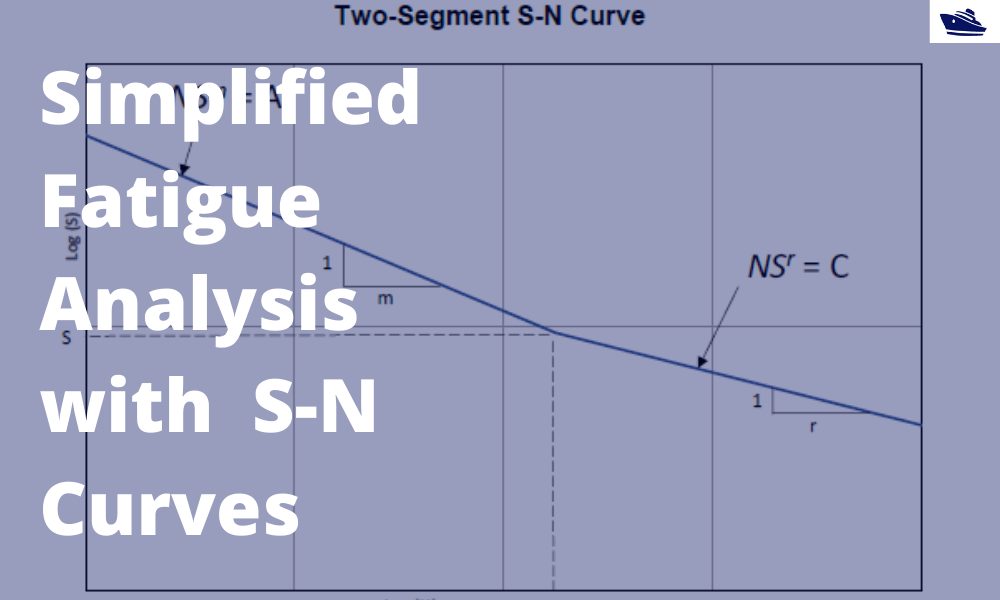
A simplified method of performing fatigue analysis of offshore structures
A simplified method of performing fatigue analysis of offshore structures Introduction An offshore structure is subject to environmental loads of waves, wind and current. By their nature, the resulting wave loads on the structure are cyclical. These cyclical...

Powering the shipping industry with hydrogen: opportunities and challenges (Part 1)
Part 1: About Hydrogen – Basics, Opportunities, and Challenges Of late, hydrogen has been generating quite a buzz in the energy sector with its possibility as a clean source of energy. The shipping sector is not untouched, and this article explores the possibilities...
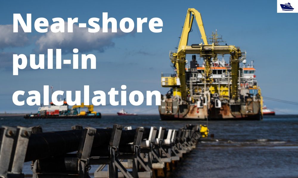
The importance of analysis in nearshore pull-in operation in offshore wind farms
Introduction Over the last 10 years, the global wind energy business has increased manifold. In the next 5 years, the rate of installation is expected to accelerate. This is mostly driven by the opening up of Chinese and US markets. A primary chunk of this market is...

Vessel Draft Survey Accuracy
by Chris Zeringue, Owner, MTS Marine Techincal Surveyors The key to accuracy in a Vessel Draft Survey may very well be found in a hole in the ship. I boarded my...

How to use a ship’s hydrostatics to calculate its draft and trim
Introduction A ship’s hydrostatics, or hydrostats, is an oft used term in maritime parlance, and it refers to the characteristics when it is floating. What characteristics are these? How are these determined, and how can we read and understand them? Understanding...
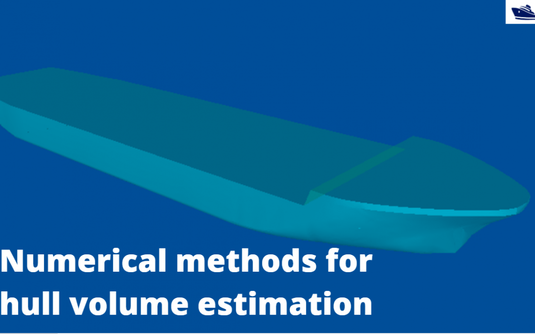
Numerical integration methods for hull volume estimation
Introduction The hull of a ship is a complex 3D geometry, and finding out its simple properties like volume, centroid, etc. is not possible through simple formulae unlike standard shapes like cuboid or a cylinder. How do we find a property, say the volume of a...
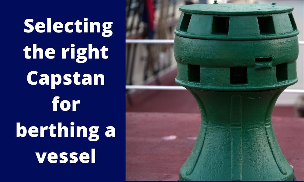
Selecting the right Capstan for berthing a vessel
Introduction Capstans are frequently deployed mooring equipment used on all types of vessels. Capstans are berthing/mooring equipment used to multiply the pulling force on mooring ropes. Traditionally, Capstans were operated manually but in modern ships, they are...
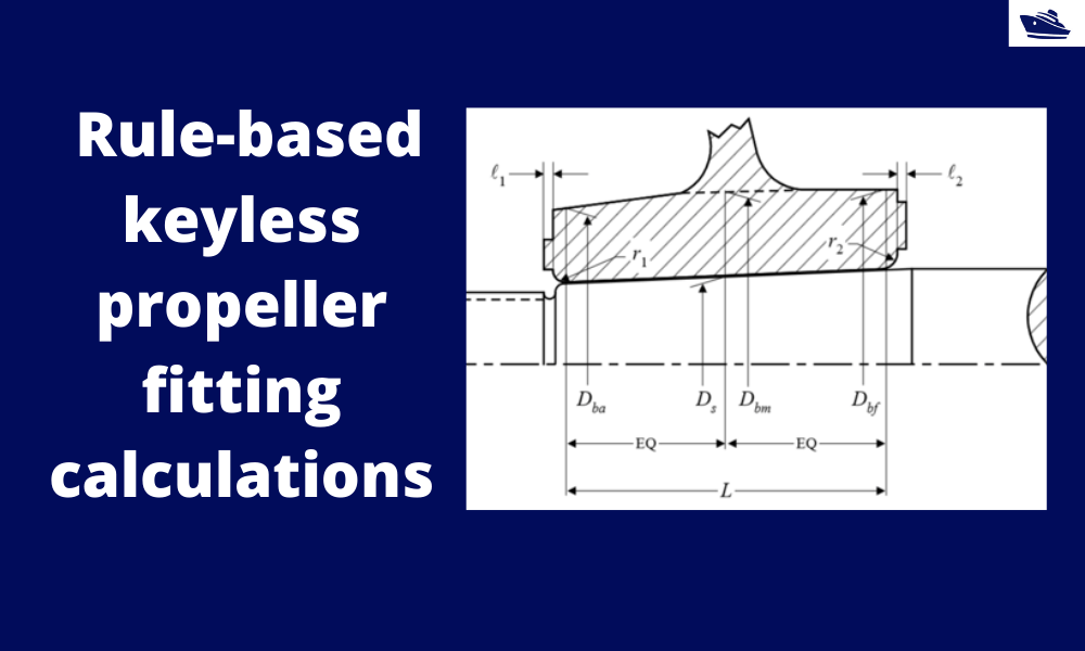
How to do rule-based fitting calculations of a keyless propeller
Introduction A keyless propeller, as the name implies, requires no key for fastening the propeller on the cone of the propeller shaft. How is the torque then transferred to the propeller? The torque is transferred by the friction between the propeller and the...

Grazie. Tutto molto interessante
hello thanks you