Intriguing as it sounds, Equipment Number (or Equipment Numeral) throws a plethora of questions when heard for the first time. Is it something which tells the number of equipment on a ship, or is it a catalog which assigns specific number to the equipment on a ship?
Cutting to the chase, Equipment Number (abbreviated as EN) is just a non-dimensional parameter which can be used to select the right sized anchoring and chain cables for a new ship. However, it is to be noted that these equipment are only meant for harbor mooring, and not for open sea or rough weather mooring.
Once the EN is known, a set of adequately sized equipment for mooring/anchoring of the vessel can be selected. Following are some equipment which can be selected based on EN:
- Stockless bower anchors
- Stud-link chain cables
- Towlines – made of Steel of fiber ropes
- Mooring lines – made of steel or fiber ropes
First Principles
Thinking in very basic terms, the problem at hand is to select the right set of equipment for anchoring/mooring a vessel at port/harbor. That brings us to the basic question – why do we need to anchor a vessel? The simple reason is to prevent it from drifting away. What causes the drift? It is the forces of the environment acting on the vessel. What are these forces? The forces are wind, current and wave. Wave is generally non-significant at harbors.
How is wind/current force on the vessel calculated? Wind and current forces are drag forces, and they follow the simple drag equation
F = ½ x ρ x V2 x A
where, F = drag force, ρ = density of the medium (air/water), V = speed of wind/current, A = Area of vessel exposed to wind/current
From the above formula, we can understand that the Area of the vessel exposed to the wind or current is a critical input in calculation of the drag force. Inferring further, Wind force will depend on the projected windage area of
- the hull above the waterline, and
- topsides/superstructure/deckhouses
Current force will depend upon the wetted surface area of the hull underwater
Analysis
Now that we know the basis of the calculation, let’s move on to establish the how a number (the Equipment Number) can be used to gauge the environmental forces for a vessel.
One thing is clearly obvious – that a bigger ship will have higher windage and current areas, and thus will attract higher forces. Similarly, a smaller ship will have smaller forces. These forces depend upon the projected areas, which become the determining parameter.
Also, we can infer that a ship with higher forces will need heavier equipment to anchor itself.
Thus, we can establish the following relationship
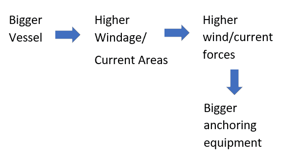
The above relationship is good to know but is obvious and not really spectacular or particularly helpful in selecting the anchoring or mooring equipment. The question remains – How do we select the right size equipment?
Do we go about calculating the forces for each port/harbor the vessel is expected to dock at? That will be a tedious exercise.
Won’t it be great if there was some standard table which recommends the equipment size based on the size of the vessel? That would make our lives much easier. Say, given the windage/current areas of the vessel and its topsides/superstructure, the table can belt out the sizes of anchors and cables to be used. Further, it will be much better to combine both windage and current areas as one input against which the equipment sizes can be presented.
The windage and current areas are combined in a number called Equipment Number (EN). The table which gives the sizes of anchoring/mooring equipment for various Equipment Numbers is called the Equipment Number/Numeral (EN) Table. EN Tables are provided in most Classification Society rules and the formula to calculate the Equipment Number (EN) is also provided.
For example, the DNV-GL rules provide the formula and table for EN in its Rules for Ships, Part 3, Chapter 11, Section 1-3. An extract of the EN formula is presented below:
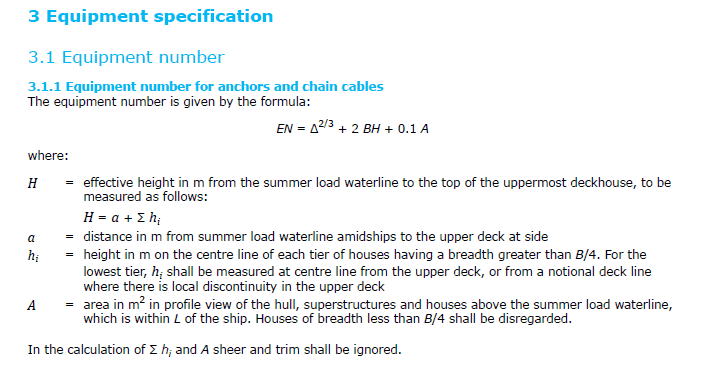
Δ = Rule Displacement in MT
Let’s analyze the formula.
The formula is a sum of the different components of current and windage areas.
- The first term, Δ, is the vessel displacement. This term, being the weight of the underwater portion of the ship, relates to the area exposed to current forces (the displacement raised to the power of fraction 2/3 factors the cubic displacement term to a squared area term, roughly)
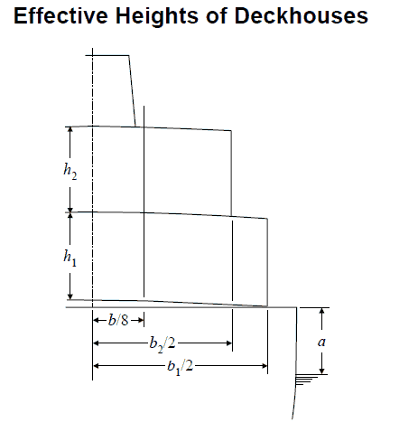
- The second term 2 BH, is an indicator of the transverse windage area of the vessel. We can see that H is the height of effective height of the uppermost deckhouse. Calculation of H has two parts:
- The part representing the hull exposed to wind – captured by the term ‘a’
- The part representing deckhouses – captured by adding the heights of deckhouses present on the vessel.
The following diagram from ABS Rules Part 3, Ch 5, Sec 1/3.5 demonstrates the calculation of H. Only deckhouses which have width greater than B/4 (B = breadth of the vessel) are considered in the calculation
- The third term 0.1A, is an indicator of the profile windage area of the vessel. The profile area is not a governing one for windage area calculation, as the anchored vessel will weathervane to face the wind direction, and thus the transverse windage area of the vessel governs. Thus, the profile area is factored by the value 0.1. When EN has to be calculated to select the towing or mooring lines, then the area A has to additionally include the profile area of the maximum stacks of deck cargoes above the summer water line.
We can see that EN is obtained as a numerical value from the above formula and has the units of area (m2). Also, the value obtained from the above formula should be rounded off to the nearest higher integer to get the EN.
Getting equipment sizes
Once we have the EN, what next? How do we select the right sized equipment from EN? Once again, Class rules come to assistance.
Class Rules provide standard tables for getting the equipment sizes once the EN has been calculated.
Once such table for DNV Rules is shown below:
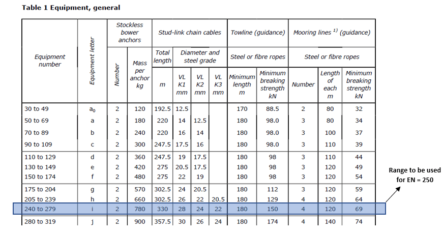
We can see above that the first column has different ranges of Equipment Number (EN). Every EN range is allotted an equipment ‘letter’ which is an alphabet (sometimes with a subscript). This is a notation used for classifying the equipment based on equipment number.
The above table is straightforward – from the value of EN, we locate the correct range in the first column. For example, if the EN is 250, then the range to be used is 240 – 279, as highlighted in the table above.
It is to be noted here that for the same vessel, the EN to be used for Towline and Mooring line selection can be higher compared to the EN used for the rest of the equipment (cables and anchors), since additional profile areas of deck cargoes are also included while calculating EN for towline/mooring line selection.
Exceptions and deviations
- For fishing vessels with EN up to 720, the table to be used is separate. For EN above 720, the regular table can be used (as per DNV rules, Ref [2])
- For vessels operating in harbored/restricted service areas, the EN can be reduced. Please see DNV Rules (Ref [2]) for more details.
References
[1] https://www.wartsila.com/encyclopedia/term/equipment-number[2] DNV Rules for Ships, Part 3 Hull Chapter 11 Hull equipment, supporting structure and appendages
[3] ABS Steel Vessel Rules, Part 3, Ch 5, Sec 1, Anchoring, Mooring and Towing Equipment
Please do take a moment to explore our product on Equipment Numeral Calculation:
Disclaimer:
Disclaimer:
This post is not meant to be an authoritative writing on the topic presented. thenavalarch bears no responsibility for the accuracy of this article, or for any incidents/losses arising due to the use of the information in this article in any operation. It is recommended to seek professional advice before executing any activity which draws on information mentioned in this post. All the figures, drawings and pictures are property of thenavalarch except where indicated, and may not be copied or distributed without permission. The views, information, or opinions expressed in the article are solely those of the author and do not necessarily represent those of TheNavalArch Pte Ltd and its employees
Naval architecture, new challenges and a new horizon
Naval architecture, new challenges and a new horizon by Lim Soon Heng, BE, PE, FSSS,...

Mooring System Design and Analysis
Mooring System Design and Analysis by Rahul Kanotra, Consultant Naval Architect As the offshore...
Cargo Stoppers – why they are critical and how to design them
Stoppers and their critical role in seafastening of cargo Introduction A cargo transported on the...
Are you chartering a tug bigger than necessary for your Barge?
Barges are one of the most frequently used means for transporting...
Fendering – an Introduction
In this two part article we will talk about Fendering, which is one of the basic but critical...
Loadouts – An introduction
Image source: Flickr Loadout Operations - an Introduction Loadout is a term oft heard of in the...
Introduction to Pipe Transportation – Part 3 (Engineering)
Introduction to Pipe Transportation - EngineeringIn Part 1 we learnt about pipes,...
Introduction to Pipe Transportation – Part 2 (Planning & Scheduling)
In Part 1, we looked at the properties of pipes. In this section, we will be looking at the...
Pipe Transportation – An Introduction (Part 1)
(To read Part 2, click here) This is the first part in the 3-part series on Pipe Transportation....
Ship Corrosion – Cathodic Protection and Sacrificial Anodes
CATHODIC PROTECTION ON SHIPS – SACRIFICIAL ANODES Image Source: pixabay SECTION 1 –...

Dears do you have any calculus about Silencer of exhaust gas choices?…..
Thank you un advance
Thanks for the query Ariel. Will get back by email
About equipment number calculation detail instruction.