Introduction
A keyless propeller, as the name implies, requires no key for fastening the propeller on the cone of the propeller shaft. How is the torque then transferred to the propeller? The torque is transferred by the friction between the propeller and the propeller shaft.
In this article, we’ll see what important parameters govern the design of a keyless propeller, and how these can be calculated.
These are based on ABS Rules for Building and Classing Steel Vessels 2019, Part 4 Vessel systems and machinery, Section 3 Propellers. Class rules require a minimum factor of safety against the slip of 2.8, which can be used to calculate the maximum pull-up load. This load also depends on several other parameters like the type of propulsion, diameters of boss and hub, rated thrust, etc. that have been discussed below.
Design Parameters
The following design parameters are important for the keyless propeller design:
- Minimum required mating surface pressure
- Minimum pull-up length
- Pull-up Load
- Dry-fitting
- Wet-fitting
- Contact surface pressure
- Hoop stress
- Equivalent stress
Parameters like mating surface pressure and pull-up length also depend on the temperature of operation.
Design Criteria
The design criteria as per ABS rules are as follows:
- The factor of safety against the slip of the propeller hub on the tail shaft taper at 35°C (95°F) is to be at least 2.8 under the action of maximum continuous ahead rated torque plus torque due to torsional vibrations.
- The maximum equivalent uniaxial stress (von Mises-Hencky criteria) in the hub at 0°C (32°F) is not to exceed 70% of the minimum specified yield stress or 0.2% proof stress of the propeller material.
- The calculations submitted must cover the following parameters:
- Theoretical contact surface area
- The maximum permissible pull-up length at 0°C (32°F) as limited by the maximum permissible uniaxial stress specified above
- The minimum pull-up length and contact pressure at 35°C (95°F) to attain a safety factor against slip of 2.8
- The proposed pull-up length and contact pressure at the fitting temperature
- The rated propeller ahead thrust
Inputs
The calculations will require multiple inputs related to the propeller’s geometry and material, along with the vessel’s parameters like speed.
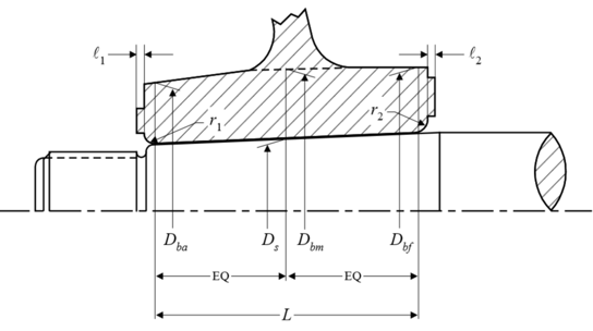
The inputs all follow the rule requirements by ABS, and are listed below. The diagram below also depicts some of the inputs.
- Contact surface area between propeller hub and shaft taper (A)
- Coefficient of friction between mating surfaces (µ)
- Half taper of shaft (θ)
- Factor of safety against slippage at 35°C (S)
- Coefficient for type of propulsion drive (c)
- Outer diameter of hub corresponding to Ds (Dbm)
- Outer diameter of hub corresponding to the forward point of contact (Dbf)
- Outer diameter of hub corresponding to the aft point of contact (Dba)
- Mean outer diameter of hub corresponding to Ds (Db)
- Diameter of shaft at mid-point of the taper in axial direction (Ds)
- Mean propeller pitch (P)
- Rated propeller thrust
- Calculated based on Power at rated speed (H), Vessel speed at rated power (v), and Rpm at rated speed (R), OR
- from designer (T-User)
- Modulus of elasticity of hub material (Eb)
- Poisson’s ratio of hub material (νb)
- Coefficient of linear expansion of propeller hub material (αb)
- Modulus of elasticity of shaft material (Es)
- Poisson’s ratio of shaft material (νs)
- Coefficient of linear expansion of shaft material (αs)
- Yield stress or 0.2% proof stress of propeller material (σy)
- Reference temperature as per rule (tref)
- Contact length (L)
Calculations
The formulations for the various parameters are shown below:
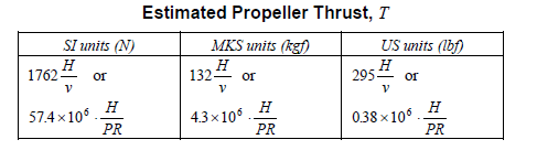
- Rated propeller thrust – if the designer has this value, then the designer’s value is used, else the value from rules can be used
- Rated Torque – Q is the rated torque which is an input corresponding to H & R, however, it can be estimated from the formula below
![]()
- Shear force at the propeller-shaft interface

- Pull-up length
The minimum pull-up length is taken at 35 degrees C, and is given by

The minimum pull-up length at any other temperature (less than 35 degrees) is given by

- Minimum mating surface pressure at 35 degrees C is given by
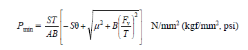
The minimum mating surface pressure varies with temperature, and at another temperature less than 35 degrees C, it is given by

Here δmin and δt are the pull-up lengths at 35 deg and at temperature ‘t’ respectively.
- Pull-up load
The pull-up load can be calculated using the formula below:
Wt (pull-up load) = A x Pt (μ + θ), where
μ = coefficient of friction between mating surfaces. For wet fitting, the friction is considerably lower than dry fitting
θ = Half taper of shaft
- Stresses: The hoop stress and equivalent stress can be given by:
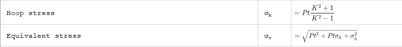
where K is the ratio of Db and Ds
That brings us to the end of this article. TheNavalArch also has its own product which simplifies the above calculations for the user. Please do check it out
References
- ABS Rules for Building and Classing Steel Vessels 2019 , Part 4 Vessel systems and machinery, Section 3 Propellers
- https://trid.trb.org/view/63325
Disclaimer: This post is not meant to be authoritative writing on the topic presented. thenavalarch bears no responsibility for the accuracy of this article, or for any incidents/losses arising due to the use of the information in this article in any operation. It is recommended to seek professional advice before executing any activity which draws on information mentioned in this post. All the figures, drawings, and pictures are property of thenavalarch except where indicated, and may not be copied or distributed without permission.
https://thenavalarch.com/software/maritime-industry-thenavalarch/ship-design/resistance-propulsion/keyless-propeller-fitting-calculations/

Autonomous ships of the future
Automation is in good servant but a bad master!By Dr L R Chari, ex-Executive Director of Shipping Corporation of India (SCI)*This article originally appeared in June 2018 edition of Marine Engineers Review (India), the Journal of Institute of Marine...

The digital transformation of the maritime domain
(This article originally appeared in June 2018 edition of Marine Engineers Review, Vol 12, Issue 7, Journal of The Institute of Marine Engineers (India), and is being reproduced here for readers of TheNavalArch's blog)The maritime domain is gradually...
Selecting the right gear for towing operations – Part 1
Towing operations seem pretty straightforward – we just need to connect the vessel to be towed to the right sized tug and get started! However, a simple exercise of digging deeper will reveal critical items that we need to take care of. If we start thinking about the...
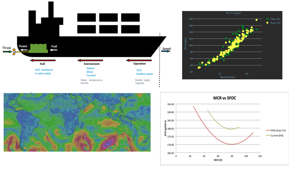
Removing Human Error in Ship Performance Analysis
Introduction Shipping is the most dominant means of transport that facilitate global trade. Over 90% of world trade is done by ships[1]. Fuel onboard ships, commonly referred to as "bunkers", has become the largest cost item of a ship's Operational Expenses (OPEX),...
OCIMF MEG-4 and Mooring Design of your vessels – Part I
Part 1 – Environment and Environmental forcesThe OCIMF (Oil Companies International Marine Forum) has come out with the latest edition of mooring Equipment Guidelines (MEG) – Rev 4. This revision incorporates significant changes and updates over the MEG-3,...

Equipment Numeral Calculation for a Ship – a Guide
Intriguing as it sounds, Equipment Number (or Equipment Numeral) throws a plethora of questions when heard for the first time. Is it something which tells the number of equipment on a ship, or is it a catalog which assigns specific number to the equipment...
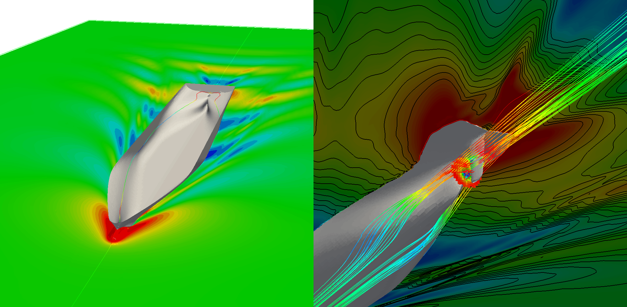
CFD in the marine industry: today and tomorrow
In the world of advancing digital technology, it important to identify all the best ways to apply it to the extremely complex task of designing a ship. Riding the wave of the rapid progress of High Performance Computing, Computational Fluid Dynamics (CFD)...
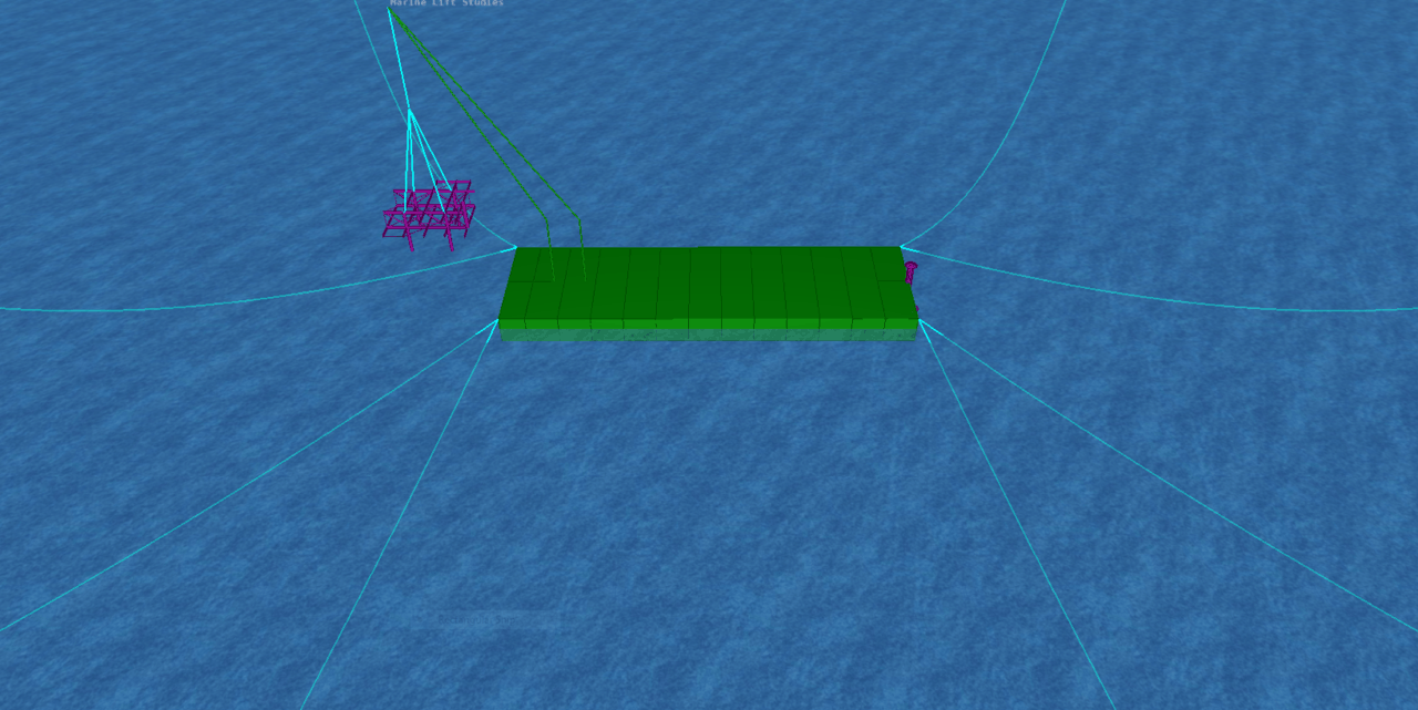
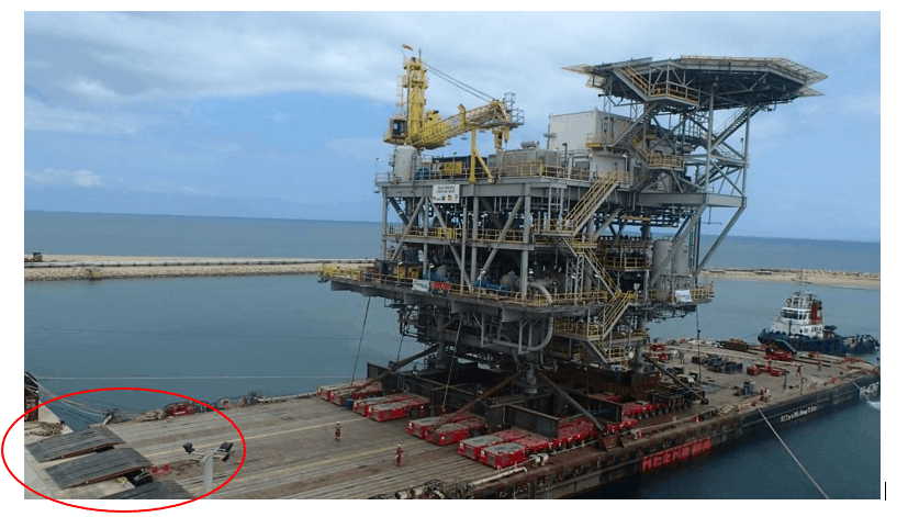
Marine Lifting – Engineering and Planning
Ever since the offshore industry has expanded to deeper waters, one topic of broad and current interest, that has dominated the industry, is the weight of topsides lifted offshore. Installation contractors advertise engineering feats accomplished by...

Transportation Analysis for deck cargo – complete breakdown
Introduction In the simplest terms, Transportation Analysis is the complete design and engineering which goes behind making a transportation operation successful. In this post we'll talk about transportation of project cargo over deck. Such cargo can be equipment,...
Loadout Ramps – design and analysis of the simplest flat plate ramp
Loadouts are a complicated exercise and require intricate engineering calculations to ensure success of the operation. Right from selecting the suitable vessel with adequate ballasting capability, to performing ballasting and stability calculations,...
