Introduction
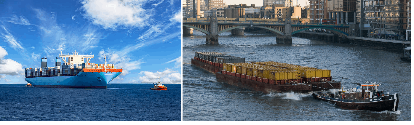
In the simplest terms, Transportation Analysis is the complete design and engineering which goes behind making a transportation operation successful. In this post we’ll talk about transportation of project cargo over deck. Such cargo can be equipment, modules or other heavy structure (like a jacket or a crane being transported). A visualization of the entire operation appears quite simple – place the item on the deck of the vessel, move the vessel to its destination, and unload the item. However, depending on the size and geometry of the cargo, the whole operation can involve deeper intricacies which require careful engineering calculations and analyses. In this article we breakdown the steps involved in doing a complete transportation analysis. This may or may not be applicable to all vessels or cargo, but it can give a fair idea to avoid common pitfalls of engineering during marine transportation.
Steps of Transportation
![]()
In general, the following steps are followed for any deck cargo transport:
- The Cargo is lying on quay side and is loaded to the vessel. This step is called ‘loadout’
- After loading on the vessel, the cargo has to be secured to the vessel. This step is called ‘Seafastening’
- The vessel motions and stability during the voyage have to be pre-assessed
- Upon reaching the destination, it has to be loaded in from the vessel to the quay/port. This step is called ‘load-in’
Digging deeper
If we dig deeper and think more analytically, following are the questions which may become relevant for each step
- During Loadout/Load-in
- Is the vessel big enough to accommodate the cargo?
- Even if the vessel if big enough, is it strong enough? Will its deck be able to withstand the load of the cargo?
- How will the transfer from quay to vessel be done? Will the cargo be lifted, will it be skidded or transferred using a SPMT trailer?
- Will the vessel stay stable during the loadout/load-in? How will we ensure it is at even keel during the process?
- After Loadout from Quay to vessel
- How will the cargo be secured to the deck? Will it be lashed using ropes, or will it be welded to the deck?
- How many lashings to be used? How strong should the lashings be?
- How to spread out the cargo load on the deck? What should be the ideal location where the cargo legs should sit?
- During the transportation
- How to maintain the stability of the vessel during the transport?
- How will the cargo be affected by environmental forces of wind, wave and current? How to estimate how much load will come on to the cargo from these forces? How will they impact the design of the seafastening?
- How will the vessel move? Will it use its own propulsion, or will it be towed? How to select the right tug, if it is to be towed?
Breaking it down
![]()
Here we break down the steps of engineering which are performed for a successful transportation operation. Again, not all of them may be applicable to all operations, and we can pick and choose depending on the complexity of the operation.
Additionally, it should be noted that all these analyses and calculations must be performed much prior to the actual operation and passed on to the operations team and approving authority (generally Marine Warranty Surveyor).
- Ship or tug-barge? Whether to use a self-propelled ship or a tug-barge combination is generally a commercial decision and taken at the very initial stage
- Space check – The vessel must have clear deck space to accommodate cargo. However, that’s not enough – the deck space should be sufficient to add lashings to the cargo on the sides and ends. An initial look on the locations of lashing points on the cargo can give a good idea of the space needed for lashings
- Deck strength – A quick check to see if the deck of the vessel is strong enough can be made by looking at the vessel’s specification sheet. The deck strength is specified in units of tons/m2. Given the weight of the cargo and its footprint on the deck, we can calculate the deck load due to the cargo. This deck load should be within the deck strength limit of the vessel. While this may not be a very good parameter to judge any point loads the vessel may experience, it is still a good parameter to gauge the vessel’s strength sufficiency in vessel selection stage. For the final transportation analysis, a thorough assessment of the deck strength (beam analysis or FEA if needed) must be carried out
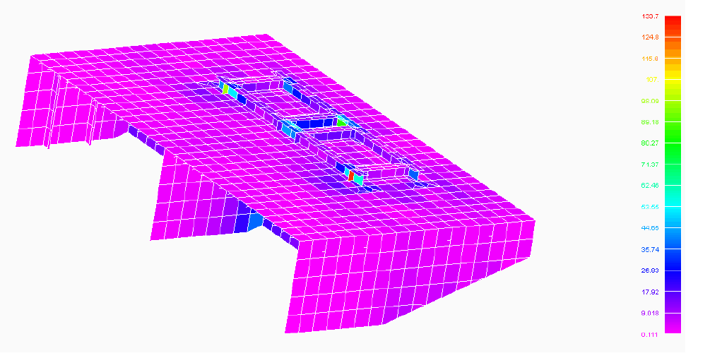
FE Analysis of a deck structure
- Loadout capability and strength: If the loadout is a lifted loadout, then the loadout operation is simple and doesn’t require a detailed ballasting operation. For SPMT or skidded loadouts, the vessel must have enough ballast capability to go through the critical stages of loadout. Generally, the most critical stage is when the whole cargo has just lifted on to the vessel and is lying on the end where it has been loaded from. The tanks at the other end of the vessel must have enough ballast capacity to keep the vessel on even keel. Also, the longitudinal strength of the vessel must stay within the limits. Generally, a spreadsheet solution for preliminary checks of vessel ballast capability can be developed for preliminary assessment. However, for heavier cargo, a software solution for hydrostatics and stability (like GHS/MOSES) must be used. For heavier Cargo, it should also be noted that the foot of the cargo should sit on strong points like bulkheads to avoid any strength issues. Once the vessel has been selected, a thorough assessment of its ballasting capability, stability and strength must be performed for each stage of loadout. However, generally Loadout is a separate operation in itself and a separate loadout report is prepared. It is not generally included in the Transportation Analysis document. Design of loadout accessories like the loadout ramp also forms part of this stage
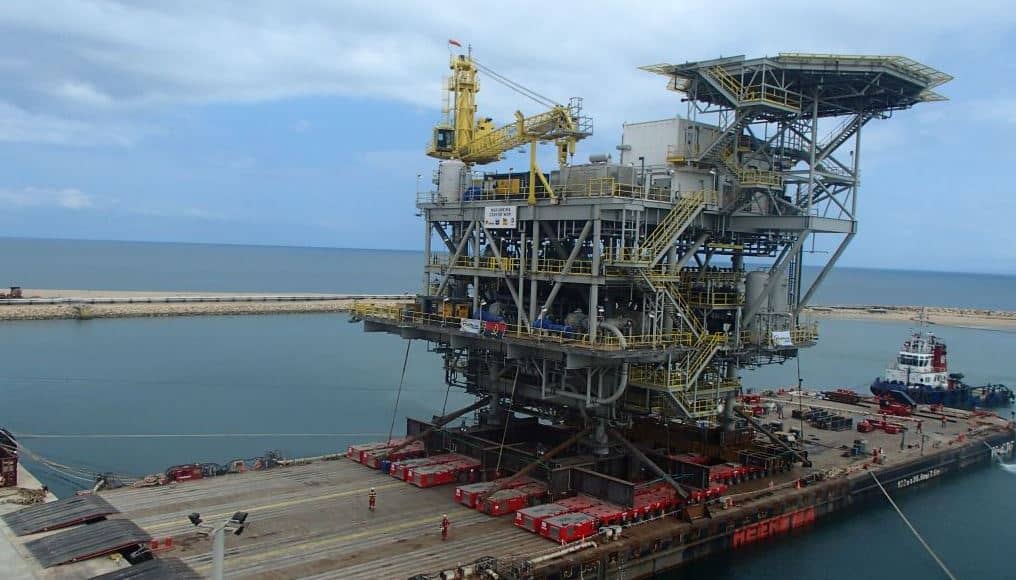
A loadout using SPMT trailer
- Transportation Stability: a check of the intact and damaged stability of the vessel during the transportation stage too needs to be performed. This may involve creating a 3D model of the vessel, performing detailed stability calculations using standard software and checking them against applicable Class rules
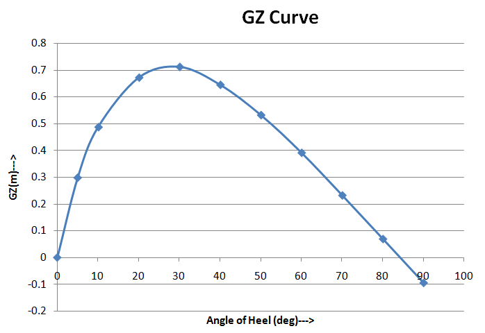
A typical Ship Stability Curve (a.k.a. GZ Curve or righting arm curve)
- Seakeeping/Motions analysis: To determine what kind of forces the cargo may experience during the transport (wind, wave, current), we may need to perform a complete seakeeping analysis, keeping in mind the worst sea state which the cargo may experience along the route. The environment data can be obtained from nautical charts or metocean data. However, during the design or vessel selection stage, a conservative estimate can be made using a simple spreadsheet application following standard guidelines like DNV-ST-N-001.
- Seafastening Design: a detailed design of lashings may not be required at the vessel selection stage, but it will be a part of the transportation analysis. The lashing design will involve design and specification of multiple lashing items:
- Lashing ropes or wires: As applicable, enough lashing ropes should be provided on sides and end of the cargo to restrain the cargo against the forces obtained from seakeeping analysis. The complete specification of ropes/wires must be provided – length, size, type, end type, material etc.
- Stoppers/clips/dog-plates: Stoppers are used to restrain the translational movement of cargo. Clips/dog-plates are used to restrain the tipping of cargo. At times they my be used in conjunction with lashings
- Shackles and pad-eyes – Shackles must be of sufficient strength to support the lashings. Pad-eyes must be designed to be installed on deck and should be checked against any out-of-plane loads.
- Stanchions: If the cargo needs to be supported by stanchions on the side, the stanchions shall be of sufficient strength. At times, a FE Analysis may be needed to affirm the suitability of stanchion.
- Dunnage: For cargo with small footprint, dunnages should be used to spread the load on the deck. Detailed check of dunnage strength should be performed to ascertain their size and suitability
- Wegdes, turnbuckles, rubber hoses – these are accessories of lashing ropes and should be provided in sufficient numbers.
- Lashing Plan: A complete lashing plan drawing showing all lashing items must be prepared and included in the Transportation Analysis document
![]()
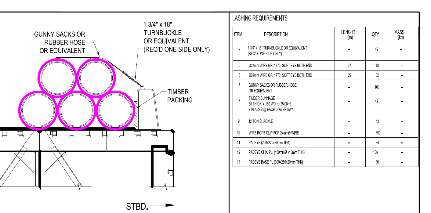
Typical lashing for transporting pipes
- Towing/Emergency towing arrangement: If the vessel is being towed, a suitable tug has to be selected for it. This will involve carrying out bollard pull calculations to select the tug. Also, a towing arrangement plan may be needed detailing the complete towing bridle and its specifications required as per standard guidelines (DNV-ST-N-001). If the vessel is a Barge, an emergency towing arrangement may also have to be prepared and submitted as part of the Transportation Analysis document.
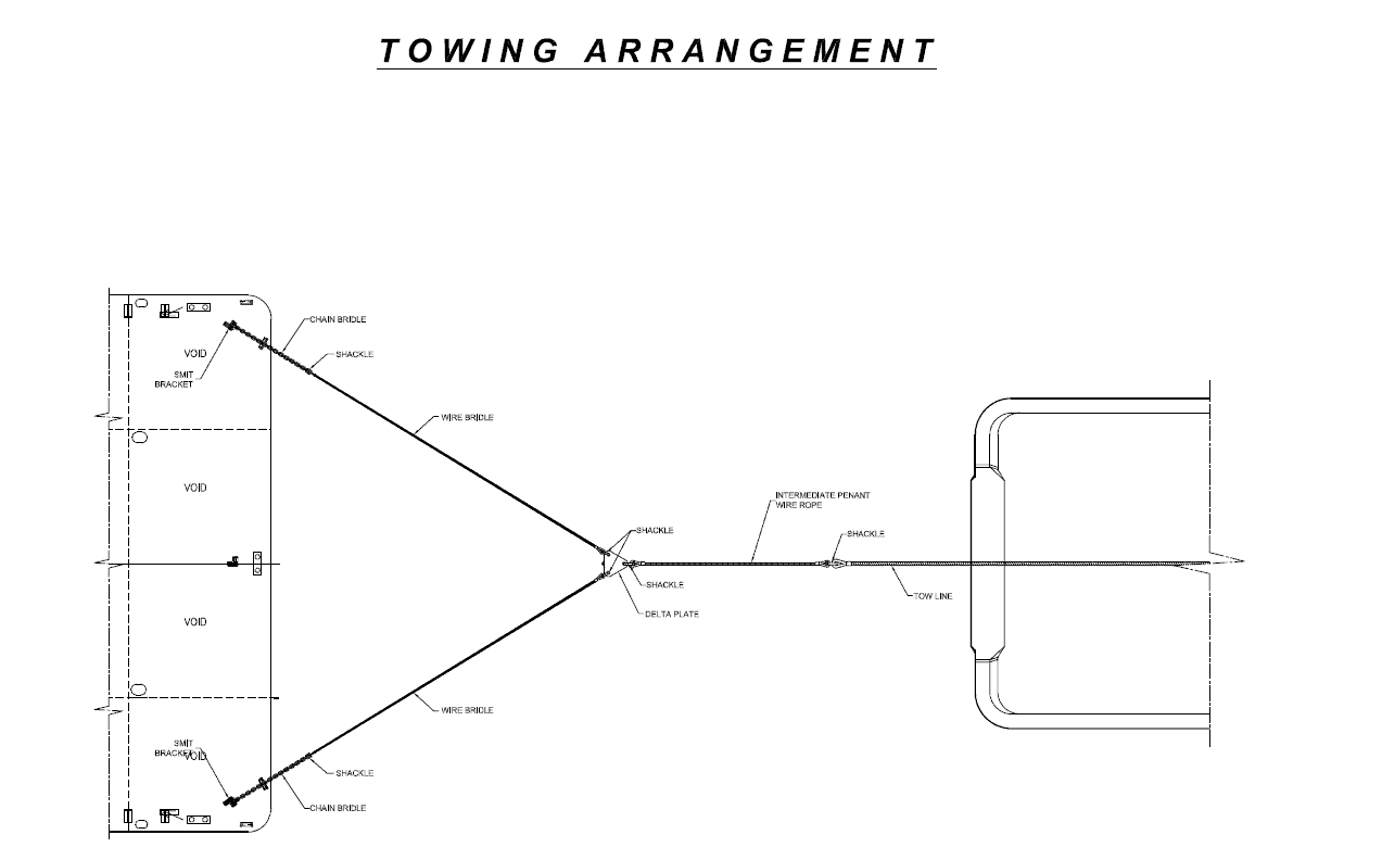
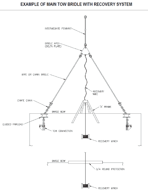
Typical Towing/Emergency Towing Arrangement (source: GL ND-0030 Rev 5)
Thus, we can see that a complete Transportation Analysis involves multiple engineering calculations and analyses which have to be performed diligently to ensure success of the operation.
Now we list down the typical contents table of a Transportation Analysis below. Please note that loadout is not included, as it is generally considered a separate operation with an independent analysis report. For each analysis performed, detailed results from software can be included in the Appendix of the report.
Transportation analysis: Typical table of contents
- Introduction: project details and what cargo is being carried
- Vessel and cargo particulars
- Tow route particulars and environment data
- Stability analysis during transport
- Intact and damaged stability
- Longitudinal strength check
- Motion/Seakeeping analysis
- Deck Strength check
- Seafastening design
- Lashing design based on seakeeping results
- Lashing plan (drawing)
- Stanchion design/check
- Pad-eye check
- Towing Arrangement design (if applicable)
- Bollard Pull calculation
- Towing bridle design
- Towing and emergency towing arrangement plan (drawing)
A thorough Transportation Analysis (TA) performed on time for an operation is a great asset to the operations team in planning and execution. While surprises are almost always guaranteed during operations, a comprehensive TA serves as a solid reference to manage them effectively.
Disclaimer:
This post is not meant to be an authoritative writing on the topic presented. thenavalarch bears no responsibility for the accuracy of this article, or for any incidents/losses arising due to the use of the information in this article in any operation. It is recommended to seek professional advice before executing any activity which draws on information mentioned in this post. All the figures, drawings and pictures are property of thenavalarch except where indicated, and may not be copied or distributed without permission. The views, information, or opinions expressed in the article are solely those of the author and do not necessarily represent those of TheNavalArch Pte Ltd and its employees

Prem Shankar
Founder
The author is the founder of www.thenavalarch.com, a website providing useful low-cost software and other online resources for Naval Architects. A graduate in Naval Architecture from Indian Institute of Technology (IIT), Kharagpur, he has worked on the design, engineering, construction and installation of a variety of marine and offshore structures, ranging from ships to offshore platforms and FPSO’s. TheNavalArch is part of his endeavour to bring rich and low-cost online content for the oil & gas and marine communities. The author can be contacted at info@thenavalarch.com
-
BargeSafe – Trim and Stability Calculator for Pontoon Barges
$499.00 Add To Cart -
Bollard Pull (Ships) with Limiting Speed
$99.00 Add To Cart -
Bollard Pull Calculations for Barge
$49.00 Add To Cart -
Bollard Pull Calculations for Ships
$79.00 Add To Cart -
Bollard Pull Calculator with Limiting Speed (Barge)
$99.00 Add To Cart -

Bollard Strength Check Spreadsheet
$39.00 Add To Cart -
Cargo Forces & Accelerations – Open Ocean
$49.00 Add To Cart -
Cargo Forces and Accelerations – Multi-Cargo
$99.00 Add To Cart -
Cargo Forces and Accelerations – Restricted
$49.00 Add To Cart -
Cargo Loading Estimator (Bulk Carriers)
$99.00 Add To Cart -

Delta Plate Design
$39.00 Add To Cart -
DNV Sea Pressure Load Calculator
$99.00 Add To Cart -
DNV Ship Motion Calculator
$99.00 Add To Cart -
Force & Acceleration Calculator – Jack-ups
$99.00 Add To Cart -
Global Wave Scatter Generator (GWSG)
$99.00 Add To Cart -
IMO Based Risk Estimator
$99.00 Add To Cart -
Lashing Design (4 Point Lashing, IMO CSS)
$49.00 Add To Cart -
Sale!
Lashing Design App (IMO CSS)
Original price was: $149.00.$99.00Current price is: $99.00. Add To Cart -
Sale!
Lashing Design App (IMO CSS) – with Stoppers
Original price was: $199.00.$129.00Current price is: $129.00. Add To Cart -
Pad-eye Design as per Eurocode 3
$99.00 Add To Cart -

Pad-Eye Design Spreadsheet
$49.00 Add To Cart -

Pad-eye design spreadsheet – with brackets
$49.00 Add To Cart -

Passage Planning – Advanced
$49.00 Add To Cart -
PassageXL: Passage Planning Spreadsheet
$39.00 Add To Cart -
PassStab: Passenger Vessel trim and Stability Calculator
$499.00 Add To Cart -
Pin Connection Design (ASME)
$39.00 Add To Cart -
Pipe Stacking Height Calculator (Bare Steel Pipes)
$39.00 Add To Cart -
Propeller Race Effect Calculator for Towing
$29.00 Add To Cart -
Ship Squat Calculator
$49.00 Add To Cart -
ShipSafe – Trim and Stability Calculator
$499.00 Add To Cart

nice one…thnks
I would like to receive the breakdown, very interresting