Gap & Sag Alignment
Gap and Sag Alignment is carried out to bring the engine to its final position, in case of directly coupled installations, and to bring the gear box to its final position in case of installations with reduction boxes. The figure below indicates a typical gap and sag alignment set up.
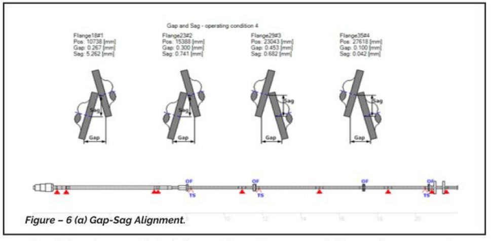
The procedure followed for the Gap-Sag is as below.
The propeller shaft forward end,(only in some cases, not mandatory) is pre loaded down, with a prescribed load at a specific Location.
In this condition, Gap and Sag values as prescribed by the maker are set between the aft flange of the intermediate shaft and the propeller shaft forward flange by adjusting the supports/bearings on the intermediate shaft.
How to measure gap and sag is a question asked many times. Experience tells, it is more accurate to measure using slip gauges and feeler gauges, as the shaft tends to move axially unless it is on self-aligning roller bearings. with thrust collars during rotation.
Once the gap sag is achieved, adjust the main engine/gearbox on jack bolts. (it is to be ensured that the engine/gearbox is supported only at the four corners during the entire alignment process)
Once both sides gap and sag is achieved, surveyed and signed off. the shafts/gearbox/engine are coupled together.
For differences of Gap-Sag between the calculated and achieved values adjustments are made using the Reaction Influence matrix.
For Direct Coupled Engines:
Normally for a direct coupled engine. the intermediate shaft will be supported on temporary supports for alignment. Once the Gap sag alignment is over, the shafts are coupled together with the engine. After this, the pedestal bearing -normally one in number, is lifted up and engaged with the shaft in way of the bearing area, using jack bolts. During this operation, a dial gauge is kept on top of the shaft at 12 o’clock position). The shaft is lifted with the pedestal bearing by 0.01 to 0.02 mm, by reading on the dial gauge. and brought down by the same amount, thereby ensuring proper bearing contact at the bottom.
Once this is done, the following are measured. Template for this, for MAN B & W engines, are attached with this annexure.
- Bearing reaction at Stern tube forward bearing
- Bearing reaction at the Plummer block
- Bearing reaction at the last main bearing
- Crankshaft deflection for the main engine
- Bedplate deflection
Since crankshaft deflection measurement is a common activity onboard operating ships, the same is not being explained in detail.
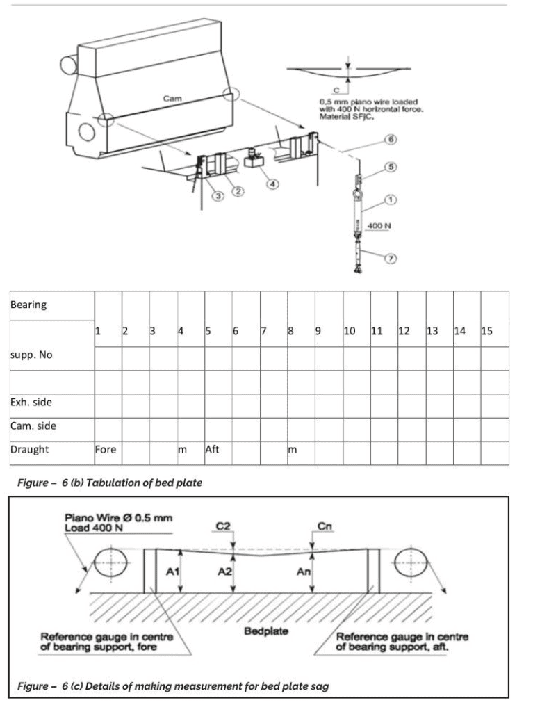
Bed Plate Deflection:
Bedplate deflection / Sag measurement and acceptance criteria are engine maker and model specific. Given above are the recommendations in this regard from MAN B &W in figure 6(b).
Bedplate sag is calculated as mentioned in the procedure above, and is to be submitted to the Engine / Propulsion maker by the shipyard. Once acceptance is received, the job can move forward.
Evaluation Of Bearing Reaction / Load
Various bearings being Loaded as intended by the design is the ultimate proof of the correctness of the alignment job. It is important to understand the method of measuring the bearing load and interpreting the same correctly for ensuring that the job is being done and evaluated correctly. In the coming paragraphs. the conducting of bearing load measurement is explained.
Alignment Verification – Jack Load Testing
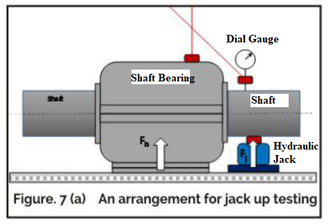
Jack Load Testing or Jack-up method is one of the methods to verify shaft alignment. By lifting the shaft at certain specific points given in the alignment analysis report, the actual bearing loads can be calculated and verified against the values specified in the alignment analysis. It is a direct, simple, and widely used method. Using a suitable jack, shaft in way of a bearing is lifted hydraulically. The load experienced by the jack is measured directly using load cells or alternatively, the recorded hydraulic pressure is converted to equivalent load units. The jack is placed adjacent and close to shaft bearings as practically it cannot be placed at exact bearing locations. Initially, as part of the Shaft Alignment calculations, the location of the jack with respect to respective bearings. expected toad to be experienced by the jack and correction factors to be applied to jack loads to obtain the bearing reactions are determined and the same are to be followed during the jack load testing.
An arrangement for jack-up testing is shown in Figure 7(a) below. The rigidity of the bearing foundation and the surface on which the jack is placed should be as specified. Also, the dial gauge is to be anchored to a structure that is not affected by the jacking up activities.
Due to the unavoidable friction in the hydraulic jack, the hydraulic pressure corresponding to a specific load will be higher during lifting than during lowering. This phenomenon is referred to as “hysteresis” (an electrical engineering term). Therefore, the load is close to measured during both Lifting and lowering, and the corresponding curve is drawn. The correct (frictionless) curve is in the center between the 2 curves drawn. Refer to Fig 7(d)

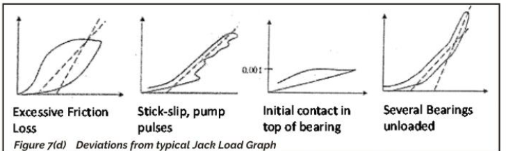
Due to the hysteresis phenomenon, it is very important that the pressure is increased steadily during the “upwards” measurement and decreased steadily during the “downwards” measurement.
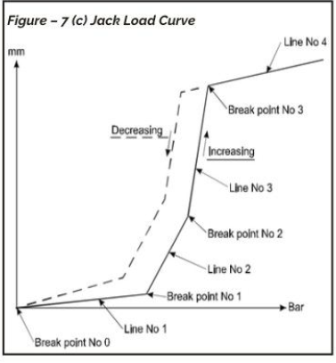
The plotted points are to be connected and normally several straight lines will occur with different slopes. See Fig. 7(c). Each time the slope changes it means that the support of the shaft system has changed.
Break Point:
- No 0: All the load is in the bearing and no load is in the hydraulic jack.
- No 1: All the load is now shifted to the jack and the bearing is fully released from the Load.
- No 2:The load in the jack is now so high that the second bearing is fully released from the toad.
- No 3: Represents the point in which the jacked journal has been lifted so high that the top clearance of the jacked bearing has been eliminated and the journal is now touching the upper shell of the bearing.
Line:
- No 1: There is load in the bearing and load in the hydraulic jack. With increasing pressure, the load is shifted from the bearing to the jack.
- No 2: With increasing pressure, the jack load is increased and simultaneously the second bearing with the load will start to be off-loaded.
- No 3: With increasing pressure, the jack load is increased and simultaneously the third bearing with Load will start to be off-loaded.
- No 4: With increasing pressure, the journal does not elevate much because the upper shell of the bearing prevents more lift.
Due to the internal friction in the hydraulic jack. there will be some difference between the corresponding values for increasing and decreasing Loads, i.e. the plotting will show two branches (hysteresis). Refer to Fig. 7 (c)
The jack load reaction (R) is the force that would be necessary to keep the shaft in its position if the bearing was not present.
In order to determine the reaction (R) two straight lines through the plotted points of the above-mentioned Line No 2 are to be drawn.
Analysis Line:
- No 1: This is a line through the increasing points of the above-mentioned line no 2.
- No 2: This is a line through the decreasing points of the above-mentioned line no 2.
- Analysis Line No 1 and analysis Line No 2 are to have approximately the same slope. Refer to Fig.7(b).
- (Ra) is the reaction of the Analysis Line No 1 at a lift of 0 mm
- (Rd) is the reaction of the Analysis Line No 2 at a Lift of mm
- The jack load reaction, Rj = 0.5 (Ra + Rd)
- The bearing reaction R is a little different from the Rj as the jack is not positioned at the center of the bearing. The Bearing reaction: R = C x Rj
For Installations With Gear Box
Once the gap and sag are cleared, shafting is coupled to the gearbox. Shafting between the gearbox and stern tube maybe with a single bearing or with multiple bearings. Temporary supports if any in addition to the pedestal bearings are removed.
Bearing reaction is measured for stern tube forward bearing, pedestal bearing/bearings, and the gearbox coupling end bearing. The template for the measurement of bearing reaction is the same as the one mentioned above.
Once all the bearing reactions are accepted. the installation is ready for chocking/Resin chocking
Once the gearbox is chocked/resin chocked and fixed. The engine is aligned to the input flange of the main engine. correcting angular and radial misalignment between the two. The limits of angular and radial misalignment are decided by the coupling employed to connect both together. In the aligned condition, crankshaft deflection of the main engine is also verified to be within limits as recommended by engine makers. At this stage, the engine is fixed using metallic/resin chocks.
Post chocking and tightening. the alignment and crankshaft deflection are re-verified and the engines are connected to the propulsion gearbox.
Alignment Of High-Speed Shafting
In some cases, the gearbox may be connected to the engine through a high-speed shafting with multiple intermediate pedestal bearings. In such cases. it is important to align all the bearings in a straight line prior to the installation of the high-speed shafting and coupling with the engine.
Acceptance of the jack loads, bedplate deflection, crankshaft deflection of the engine as applicable will mark the end of the alignment process. Various components like bearings, gearboxes, engines, etc can be fixed by chocking/resin chocking/ or by supporting devices like Vibracon or Rotochock,
Conclusion
This in short is the installation procedure of engine and propulsion systems onboard ships. There may be slight variations to the procedure, based on the shipyard’s experience and Propulsion system OEM’s requirements.
Now we will see the answer to questions mentioned at the beginning of the article
Should we re-sight the shaft line, when ships are being dry-docked for repairs?
Experience tells it is not required. unless there is a very definite indication of misalignment manifested during operation by excessive vibration, premature bearing failure, etc or there are serious mechanical damages. In this regard, it may also be noted that building the berth condition of a vessel cannot be replicated during future dry docking, and sighting may not give a conclusive answer. In case the shaft line has to be re-sighted, for reasons cited earlier, the methodology for the same is to be decided on a case to case basis, depending on the type and severity of the problem, and the repair yard’s experience in the matter.
How to re-align the shafting after the same is withdrawn for surveys?
There is no need to realign shafts when removed for surveys, most of the installations are coupled together with spigots and fitted bolts. Just connect back as original, and the system will be back to normal
What is the difference between gap-sag alignment and alignment using angular and radial misalignment?
Gap and sag alignment is basically carried out to Locate pedestal bearings, Engines (for directly coupled engines), gearbox, etc with respect to the tail shaft (Propeller shaft) forward end. Once these are located, shafts are coupled either using hydraulic couplings or with flanged joints with spigots and fit bolts. With the result, the angular and radial misalignment between shafting elements post coupling is zero. Alignment by correction of run out and face out (radial and angular misalignment), is carried out for installations coupled using a flexible coupling, capable of absorbing a certain amount of misalignment. Correction of misalignment, in this case, can be limited to the extent to which the intended coupling can absorb. In the coupled condition also, there is radial and angular misalignment between the components.
Is it important to do alignment in the middle of the night for accuracy?
It is not. Experience says that with the ambient temperature remaining nearly the same, it is ok if all critical alignment readings are done at the same time of the day, during the alignment period. However, in tropical conditions, it is preferred to do this well after sunset, as the hull will be in a better state of steadiness between Late night and sunrise.
References:
DNV Nauticus Software for Shaft whirling vibration and shaft alignment
Ship Structural Analysis and Design by Owen and Hughes
Engine alignment manuals, MAN B &W.
Authors:
Mr. Harikumar A,
Joint General Manager. Larsen & Toubro Shipyard, Chennaian active member of the Institute of Marine Engineers (India)
He has been working in the shipbuilding and repair industry since 1988. He started his career with Cochin Shipyard Limited, moved on to TEBMA SHIPYARDS, and currently works with L & T Shipbuilding Ltd. He is a graduate in engineering from Government Engineering College, Trichur. He was associated with the installation of propulsion systems of various classes of ships.
Mr. VenkataVara Prasaci Paila is a Marine Propulsion systems designer specialized in Shaft Alignment Design. In his 30 years experience, he added value to Indian Shipbuilding while drawing from 4 years overseas assignments including having worked on World’s Largest Pipe-Laying Vessel-“Solitaire”
Disclaimer: This post is not meant to be authoritative writing on the topic presented. thenavalarch bears no responsibility for the accuracy of this article, or for any incidents/losses arising due to the use of the information in this article in any operation. It is recommended to seek professional advice before executing any activity which draws on information mentioned in this post. All the figures, drawings, and pictures are property of thenavalarch except where indicated, and may not be copied or distributed without permission.
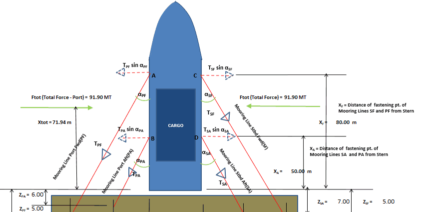
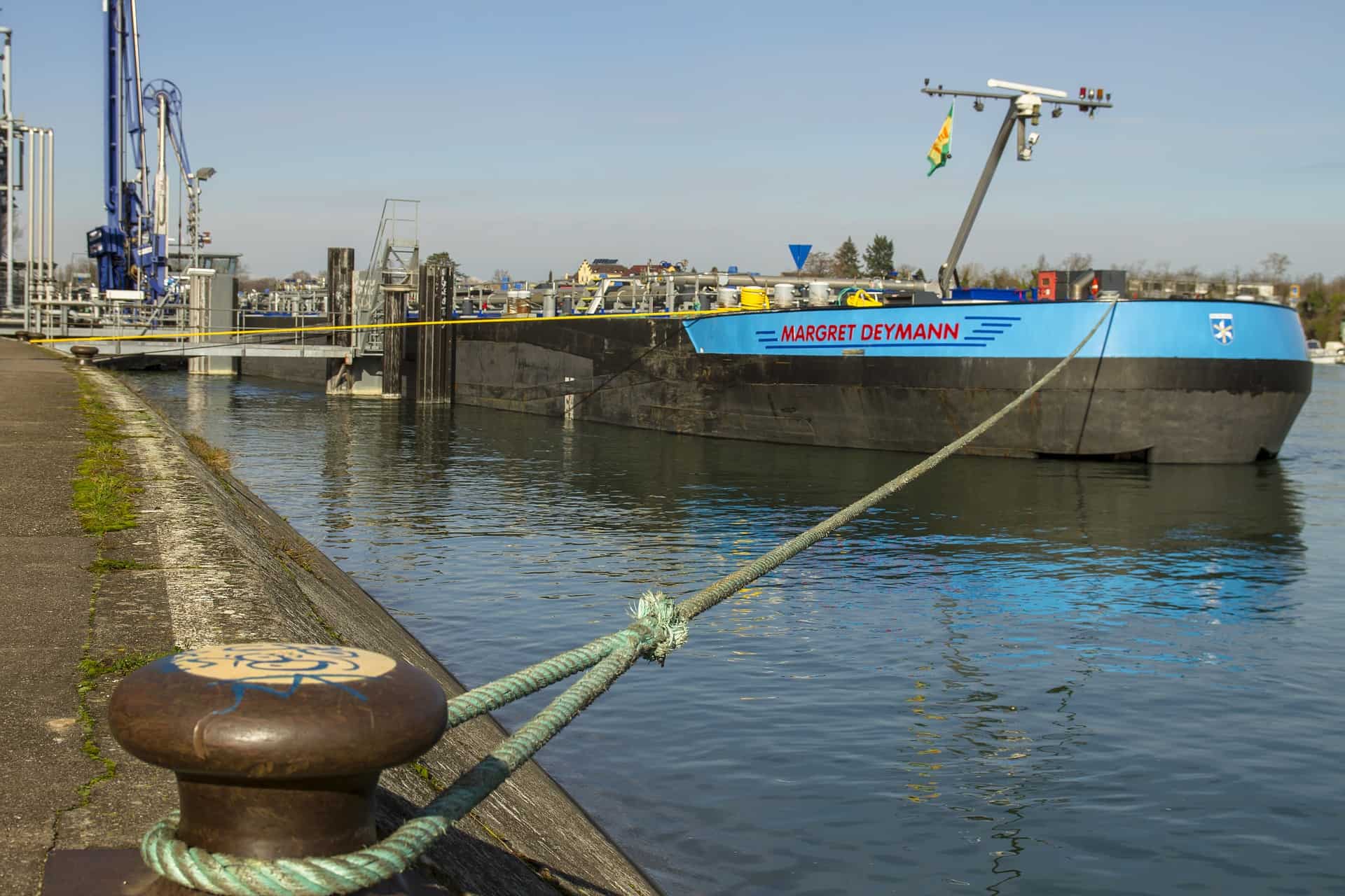
Vessel with Stern on Quay: A simplified method for mooring design
A vessel at berth experiences much lower forces compared to a vessel in the open sea due to the milder environment, but it still requires a mooring configuration suitable to the forces it experiences, and also suitable for the type of berthing configuration adopted....
Cathodic Protection – Ships, Offshore Platforms, FPSO’s and Pipelines: a comparison
Cathodic protection of a structure is an exercise which requires close study of the structure on which it is going to be implemented. The type and quantity of cathodic protection by anodes will depend upon multiple factors: the Geometry of the Structure, the...

Role of a naval architect – a walkthrough (Part – 1)
This is the first in a series of articles on 'Role of a Naval Architect' by Mr Bijit Sarkar, a Naval Architect with 35+ years of experience in ship design and shipbuilding. I would define a naval architect as one who has the ability to greet the client as he/she walks...
The bulbous bow – why some ships have it and others don’t
By Tamal Mukherjee, This is the Part 1 of a two part article on the Bulbous Bow. Part 2 can be accessed here *This article originally appeared in May 2019 edition of Marine Engineers Review (India), the Journal of Institute of Marine Engineers India. It is being...
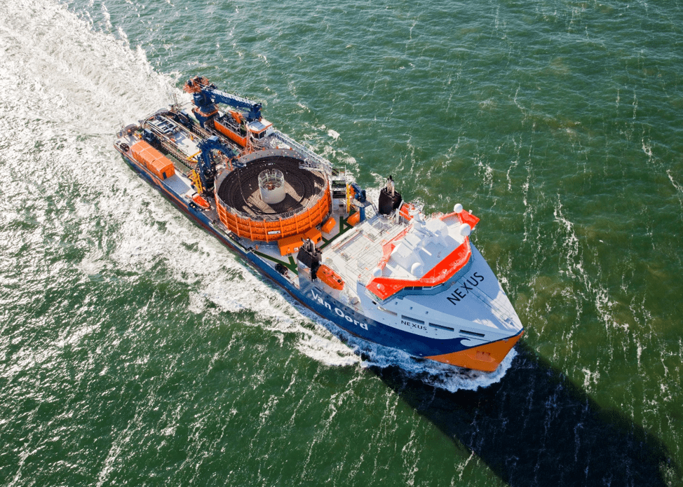
Mitigating risks during subsea cable installation
Over the last 20 years, the interest in offshore wind power generation has increased substantially. Offshore Wind Energy currently provides only 0.3% of world power generation, but the potential is really vast. In the next 20 years the offshore wind industry is set to...

A simple method of selecting the right anchor for mooring a tanker/gas carrier
Anchoring is a fundamental and sensitive operation for a vessel. When a vessel is at anchor, it swings to align itself along the direction of the dominant environment. The anchor is supposed to hold the vessel in varying environmental conditions depending on where the...
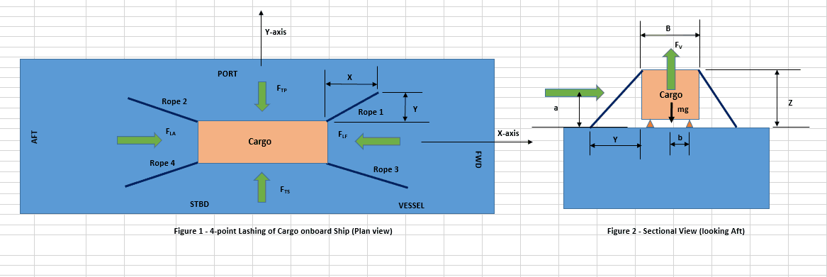
Designing a simple 4-point lashing system for a Deck Cargo
Introduction Lashing of a deck cargo on a ship involves different means and mechanisms to secure the cargo to the deck of the ship. This ‘securing’ is important to contain the movement of the cargo in view of the ship motions during the transportation. The simplest...
Calculating a Ship’s Design MBL using OCIMF MEG-4
In Part 1 of this article, we saw a step by step guide to calculate the Environmental forces on a vessel based on “Standard” environmental criteria defined in Section 3 of OCIMF Mooring Equipment Guidelines Fourth Edition (MEG-4) in order to determine the ship’s...
Selecting the right equipment for towing operations – Emergency Towing
In Part 1 of the article, we discussed the regular towing arrangements and how to select the towing gear for the same. In this part, we will discuss the components of the emergency towing arrangement and how to select them. The purpose of emergency towing equipment is...
Preliminary Rigging Arrangement Design OF 4 point, Single Hook Lifts for Non-Specialists
by Michael Harwood, PE, PMP Overview Lifting by crane is a basic construction operation that dates back to at least Sixth Century BC (ancient Greece for example) and the lifting operation itself dates back much further. It is a very common operation in present-day...

Very good information
Shafting
What is IACS requirement for final sighting after the machining of the fore and aft castings of the stern tube and press fitting of the fore and aft bearings?
Is it necessary to confirm again the shaft centre line by using all four points as they were used for the presighting? That is one point aft of the aft bearing, the center point of the aft bearing, the centre point of the fore bearing and the fore target fore of the main engine?
Or is it enough to do the final sighting after machining and force fitting of the bearings considering only the center points of the fore and aft bearings?
If the second option is enough, how it can be confirmed that the centre line between the fore and aft bearings is not misaligned with respect to the pre-sigthing centre line?
Dear Stelios, thanks for your inquiry, apologies for the delay:
IACS requires that, after machining and press-fitting, the bearing centers are verified to lie on the approved shaft centerline within tolerance.
It’s acceptable to sight only the fore and aft bearing centers, provided they’re referenced to the same original centerline/datum used during presighting.
If that datum was lost or hull deflection is suspected, a full four-point resighting should be done to confirm alignment.