Introduction
Over the last 10 years, the global wind energy business has increased manifold. In the next 5 years, the rate of installation is expected to accelerate. This is mostly driven by the opening up of Chinese and US markets. A primary chunk of this market is driven by offshore wind energy development. Such is the importance of the business that even during the COVID-19 pandemic, the wind capacity increased by 8% (https://www.iea.org/reports/renewables-2020/wind, 2020)
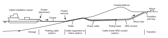
An offshore wind farm is connected to the land-based grid via a large transmission cable called Export cable. The cable is laid either from the turbines directly, or via a Transformation station located offshore towards the shore. The length of the export cable can be a few kilometers to up to 50 kilometers.
Usually, the entire cable length is stored on an installation vessel (Cable Laying Vessel CLV) which lays the cable between the shore to the substation. The ends of the cable shall be pulled in at both ends using external winches and tensioners.
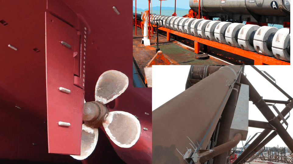
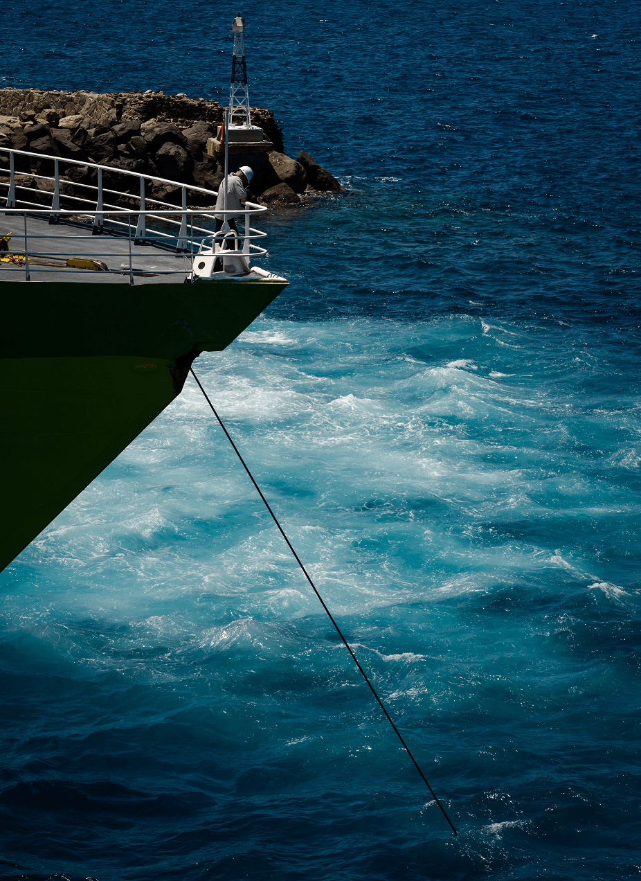
The nearshore pull-in operation is performed by pulling the cable all the way from the vessel moored /beached offshore towards the shore using a pull-in winch. The length of the cable paid out from the vessel is not dragged on the seabed, but is floated using buoyancy units. Once the cable reaches the shore, the buoyancy units are removed by personnel onshore and the cable is pulled over the rollers. There are locations where the cable could be pulled around a bent section, which adds additional frictional resistance. Lastly, the cable could be pulled underneath fixed assets (buildings, roads, railroads, dykes) through a duct (HDD). The cable is paid out using a vessel tensioner and pulled in using a winch. Sometimes, due to excessive load, additional track tensioner/winches may be installed along the path.
Challenges
Some challenges relevant for nearshore pull-in operation is as follows:
- The shallow depth on site: The operation is performed in a very shallow depth. As a result, the CLV usually cannot approach the shore due to its large draft. If the vessel does not have beaching ability (i.e. the bottom of the vessel is flat and the vessel thrusters are retracted), the vessel needs to be positioned much further away from the shore. This leads to an operational footprint spanning up to few kilometers from the shoreline (both inland and offshore).
- Friction: Due to the landside operation, a number of roller boxes are placed on the shore over which the cable is pulled over. Due to the long route length, there could be more than a few hundred roller boxes placed along the length. Due to the wet sand, tidal variations, age of roller boxes and misalignment, the rollers can be inefficient. As a result, the friction can increase considerably, leading to very high-end loads. The friction load is calculated as per Sheave formulation over a bend with angle Θ :
T=T0 eμθ
Thus the resulting friction after a bend is directly impacted by the tension before any bend.
- Current and weather window: Although the waves aren’t very significant on the shore, the current can have a significant impact on the cable drift, due to excessive drag due to the buoyancy units. A small increase in current can have a significant impact on the cable loads as not only more cable length is dragged out of the vessel, but it also linearly increases the end tension, due to the sheave friction formula, shown above. Note also that due to the shallow depth, the vessel may ground with small waves too. That’s why the operation has a restricted weather window and time is of great essence.
It is because of such challenges that the pull-in operation is closely engineered with the fullest awareness of details. Typically, the shore profile and soil characteristics are closely surveyed and roller boxes are carefully placed. The route is cleared of boulders and other obstructions. Because of any misalignment of height, there can be locations with high point loads on the vessel. These things make nearshore pull-in a critical operation. Because of its own challenges, the nearshore operation is sometimes treated as a standalone project.
Checklist
Prior to the commencement of operation, the engineers must make gross preparation to estimate the loads on the cable and the tensioners. Through a comprehensive analysis, the engineer must decide on :
- Where to position the vessel (with respect to high-low tide)?
- In which weather window can the pull-in be commenced?
- What kind of floatation do they need to use?
- How to optimize the path of the pull-in of cable?
- Where to place quadrants, winches, powered tensioners, assisting bulldozers etc.?
- HDD shape optimization?
- The capability of cable to sustain the loads?
We, at TheNavalArch, have recognized the need for a standard calculation approach for this critical operation. We have researched a simplified and median approach that can be applied across the global contractors. This not only saves precious engineering time but also eliminates errors by treating the calculation template as a check-list for any third-party verification.
Watch out this space for the upcoming launch of the tool
Disclaimer: This post is not meant to be an authoritative writing on the topic presented. thenavalarch bears no responsibility for any incidents or losses arising due to the use of the information in this article in any operation. It is recommended to seek professional advice before executing any operation which draws on information mentioned in this post. All the figures, drawings and pictures are property of thenavalarch except where indicated, and may not be copied or distributed without permission.
Vessel with Stern on Quay: A simplified method for mooring design
A vessel at berth experiences much lower forces compared to a vessel in the open sea due to the milder environment, but it still requires a mooring configuration suitable to the forces it experiences, and also suitable for the type of berthing configuration adopted....
Cathodic Protection – Ships, Offshore Platforms, FPSO’s and Pipelines: a comparison
Cathodic protection of a structure is an exercise which requires close study of the structure on which it is going to be implemented. The type and quantity of cathodic protection by anodes will depend upon multiple factors: the Geometry of the Structure, the...
Role of a naval architect – a walkthrough (Part – 1)
This is the first in a series of articles on 'Role of a Naval Architect' by Mr Bijit Sarkar, a Naval Architect with 35+ years of experience in ship design and shipbuilding. I would define a naval architect as one who has the ability to greet the client as he/she walks...
The bulbous bow – why some ships have it and others don’t
By Tamal Mukherjee, This is the Part 1 of a two part article on the Bulbous Bow. Part 2 can be accessed here *This article originally appeared in May 2019 edition of Marine Engineers Review (India), the Journal of Institute of Marine Engineers India. It is being...
Mitigating risks during subsea cable installation
Over the last 20 years, the interest in offshore wind power generation has increased substantially. Offshore Wind Energy currently provides only 0.3% of world power generation, but the potential is really vast. In the next 20 years the offshore wind industry is set to...
A simple method of selecting the right anchor for mooring a tanker/gas carrier
Anchoring is a fundamental and sensitive operation for a vessel. When a vessel is at anchor, it swings to align itself along the direction of the dominant environment. The anchor is supposed to hold the vessel in varying environmental conditions depending on where the...
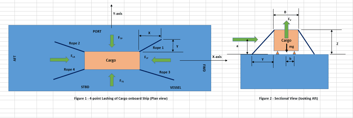
Designing a simple 4-point lashing system for a Deck Cargo
Introduction Lashing of a deck cargo on a ship involves different means and mechanisms to secure the cargo to the deck of the ship. This ‘securing’ is important to contain the movement of the cargo in view of the ship motions during the transportation. The simplest...
Calculating a Ship’s Design MBL using OCIMF MEG-4
In Part 1 of this article, we saw a step by step guide to calculate the Environmental forces on a vessel based on “Standard” environmental criteria defined in Section 3 of OCIMF Mooring Equipment Guidelines Fourth Edition (MEG-4) in order to determine the ship’s...
Selecting the right equipment for towing operations – Emergency Towing
In Part 1 of the article, we discussed the regular towing arrangements and how to select the towing gear for the same. In this part, we will discuss the components of the emergency towing arrangement and how to select them. The purpose of emergency towing equipment is...
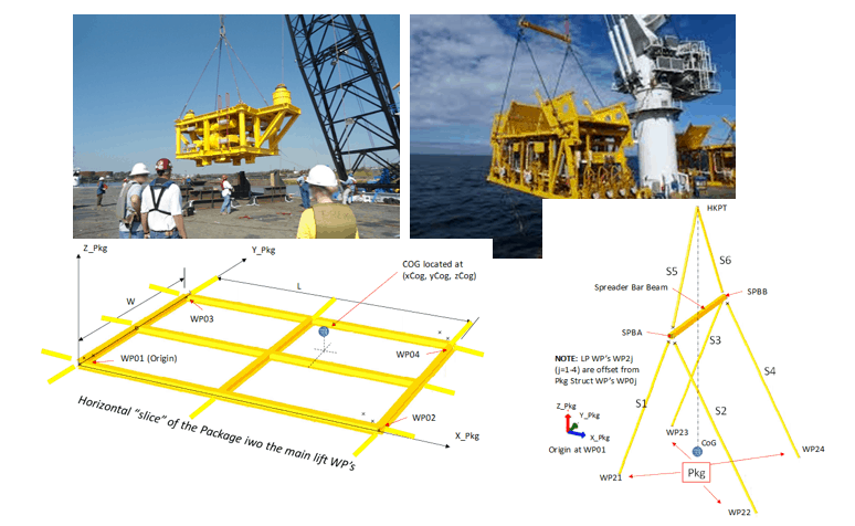
Preliminary Rigging Arrangement Design OF 4 point, Single Hook Lifts for Non-Specialists
by Michael Harwood, PE, PMP Overview Lifting by crane is a basic construction operation that dates back to at least Sixth Century BC (ancient Greece for example) and the lifting operation itself dates back much further. It is a very common operation in present-day...

many thanks