Lifting beams are universally applied gear used widely in various types of lifting operations, onshore and offshore. In this article, we will explore the design of a basic lifting beam and see what design checks are needed to establish the suitability of the beam for a particular lifting operation.
The lifting beam discussed here is one with two lifting eyes at the lower face and a single lifting eye in the middle of the upper face as shown below. The slings from the two eyes on the lower face go directly to the item lifted.
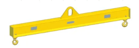
Fig. 1 A typical lifting beam
Lifting beam vs Spreader beam
At the outset, it is important to clarify the difference between a lifting beam and a spreader beam.
Lifting beams are designed to take bending loads.
We can see that it has a lifting eye at its top in the middle, while the eyes below are used to connect the slings to the lifted object. If we resolve the forces, we can immediately see that the lifting beam will be primarily under bending stress (see figure 2).
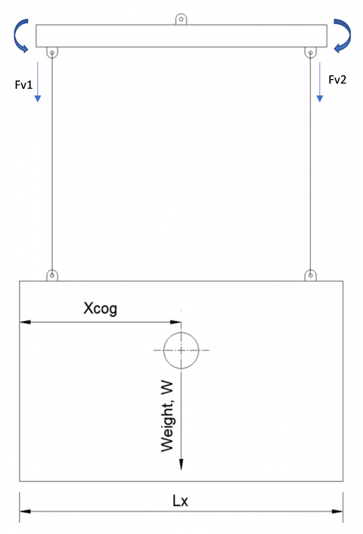
Fig. 2 Forces on a lifting beam
A spreader beam, on the other hand, is designed to take primarily compressive loads, as can be seen in figure 3.
If we resolve the forces on the whole beam, we get the force diagram as shown in figure 3. We can see that the vertical downward forces of Fv1 and Fv2 are balanced by the components F1y and F2y, while F1x and F2x are the compressive forces on the spreader. Some bending may be experienced as the forces F1x and F2x are acting at the hole of the pad-eye, which is offset from the centerline of the spreader by some distance. However, the primary load on the spreader is compressive stress. There can be lateral-torsional buckling too if it is an I-beam spreader.
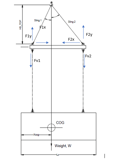
Fig. 3 Forces on a spreader beam
Lifting beams are heavier and of a bigger section compared to spreader beams to take the high bending stress. Spreader beams are generally lighter and smaller as they don’t undergo high bending stress. That said, since spreader beams require two slings on the top face each of which must make an angle of 45 degrees minimum with the horizontal, they need much higher headroom compared to lifting beams which have a single sling connecting the top eye to the lifting hook. Spreaders are useful in lifting wide loads or heavy duty loads, while lifting beams are suitable for more compact loads that don’t need a high headroom.
Loads on the Lifting Beam
Next, we analyze the loads which affect the lifting beam’s design.
Following are the loads which affect the lifting beam:
- Lifted object weight and CoG – the lifted object’s weight is to be borne by the lifting beam. Further, the location of the CoG of the lifted object has a critical effect on the sling loads. If the CoG is not located at the mid-point of the cargo (lengthwise, see Fig 3), then the loads on the slings will not be the same. The sling which is closer to the CoG is expected to take more load. Weight contingency factor and CoG inaccuracy factors are also considered as described in DNVGL-ST-N001.
- Rigging Weight – additionally, the rigging weight below the lifting beam is to be added
- Dynamic Amplification Factor (DAF) – depending on the environment of the lifting (onshore or offshore), a Dynamic Amplification Factor is to be added to the load. This can be found in DNVGL-ST-N001 (2016), 16.2.5.6
Crane Hook Capacity and Lift Point Loads
Once the loads have been finalized, the next steps are:
- Check whether the crane hook capacity is sufficient for the list. To do this, the total weight (including contingency factors) + rigging weight is factored for the DAF to give the Dynamic Hook Load (DHL). The crane hook load capacity should be more than the DHL
- Calculate the lift point loads. The bottom face of the lifting beam has two lifting points. The loads on these two lift points need to be calculated. The load is calculated from the DHL and distributed on the two lift points depending on the location of the Center of Gravity (CoG) of the lifted object along the beam’s length. The lifting point which is closer to the CoG will take a higher load, and the one further from CoG will take a lower load. See below
![]()
Stresses
The next step is the calculation of stresses. The spreader experiences the following stresses:
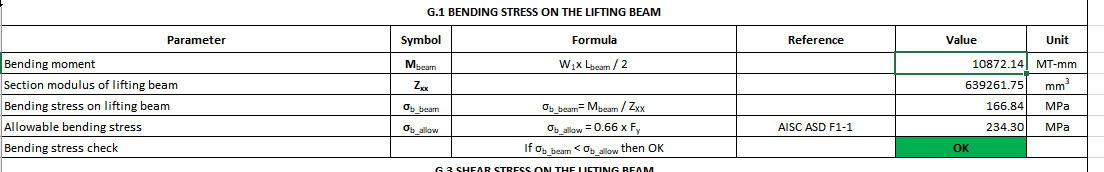
- Bending Stress – this is the governing stress of the lifting beam. This is calculated by dividing the bending moment on the lifting beam by its section modulus. The allowable bending stress is from AISC ASD F1-1.
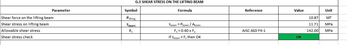
- Shear Stress – the vertical loads on the lifting points cause shear stress. Dividing these loads by the section area of the lifting beam gives the shear stress
- Lateral torsional buckling – if the lifting beam section is I-beam, then a lateral torsional buckling possibility needs to be investigated, depending on whether the flange/web is compact/non-compact. This is done as per AISC ASD Sec F2.
With all the above checks performed, a complete design assessment of a lifting beam for a specific lifting operation can be done. Lifting beams can come in different section shapes, the most common being I-beam, hollow circular, and hollow rectangular.
TheNavalArch has its own app for lifting beam design which performs all the checks diligently and can be used to either design a new lifting beam or check the suitability of an existing one for a lifting operation. Please do spend some time in exploring it through the link below.
Disclaimer: This post is not meant to be authoritative writing on the topic presented. thenavalarch bears no responsibility for the accuracy of this article, or for any incidents/losses arising due to the use of the information in this article in any operation. It is recommended to seek professional advice before executing any activity which draws on information mentioned in this post. All the figures, drawings, and pictures are property of thenavalarch except where indicated, and may not be copied or distributed without permission.

Getting the right thickness of GRP laminate for your boats
Introduction GRP laminates are widely used in the fabrication of high-speed crafts and light crafts/boats globally. GRP stands for Glass Reinforced Plastic. As the name suggests, GRP contains glass fibers embedded into a plastic resin. This gives it higher strength,...
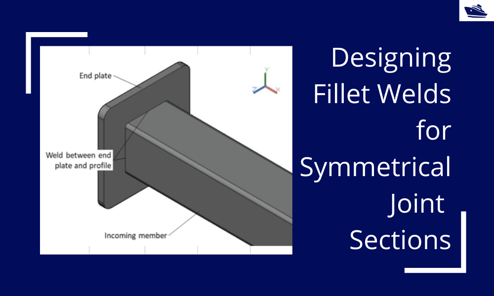
Designing Fillet Welds for Symmetrical Joint Sections
Introduction Fillet welds are the most commonly used weld types in marine structures. A fillet weld is used when there are two pieces of metal that are joined perpendicular to each other or at an angle. In this article, we will explore how to select the right size...
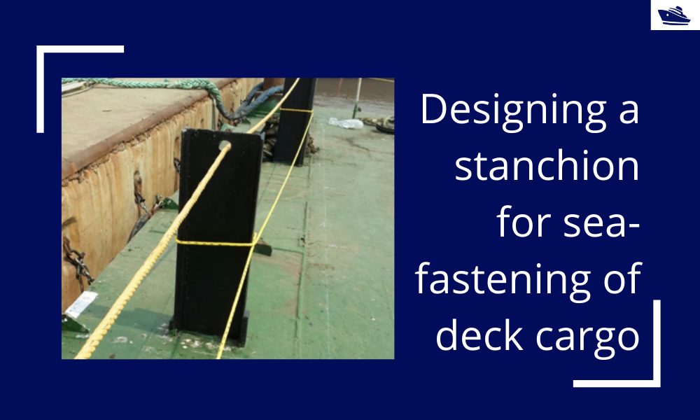
Designing a stanchion/stopper for sea-fastening of deck cargo
Introduction Stanchions – a familiar term for mariners and ship designers. What are Stanchions? A stanchion is generally a vertical pipe or beam which is used to support some structural item or provide support rails on the deck. In ships, the most common type of...

Hydrogen as an alternative fuel for ships to reduce emissions
,This article first appeared in the Feb 2019 edition of Marine Engineers Review. It is being reproduced with minor edits here for the readers of TheNavalArch's blog. Introduction The world is on facing a grave environmental challenge with an increase in carbon...

Global wave statistical analysis and its use in deepwater operations
Why do we need wave analysis? For the design of offshore operations such as installation and transport of offshore structures, as well as lifecycle design of floating and fixed structures, knowledge of extreme waves as well as the probability of different sea-states...
Designing bolts for a joint connection
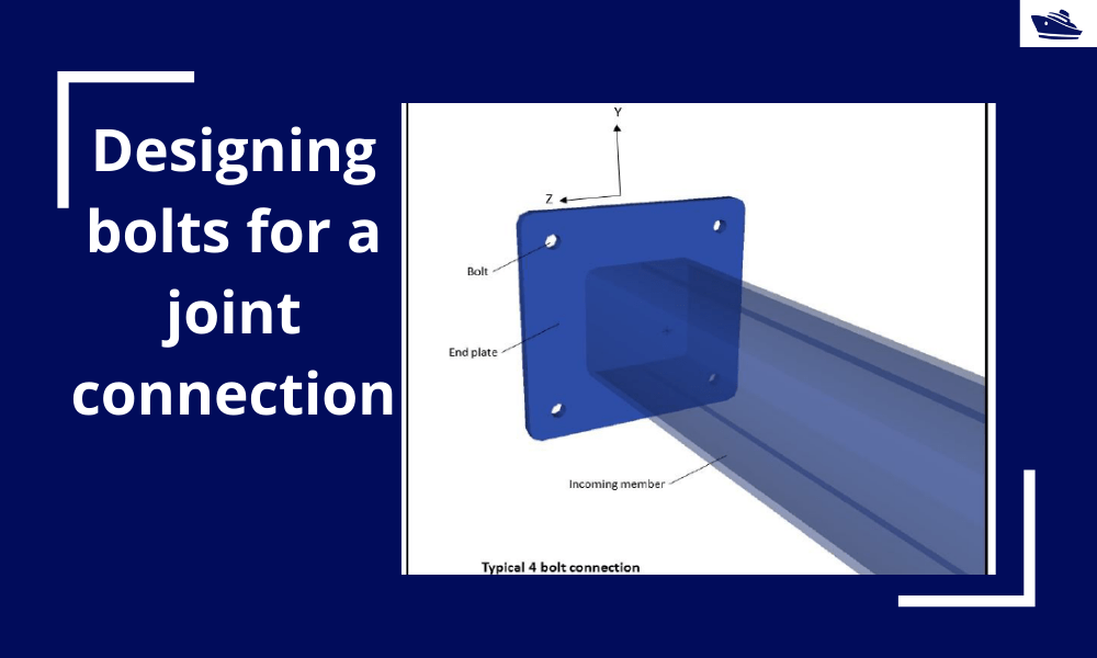
Introduction Bolts are very commonly used fastening items and used in a variety of configurations. In this article, we will explore in-depth the design of a bolt used in connecting two members at a joint (bolted joint). We'll see what properties of the bolt are...
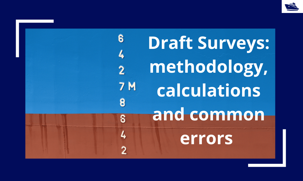
Draft Surveys: Methodology, Calculations, and common errors
Introduction Marine transport is the backbone of the global trade and reasonably can be considered to be the artery of the global manufacturing supply chain, as more than four fifths of the world merchandise trade by volume is carried by sea. Undoubtfully, the...
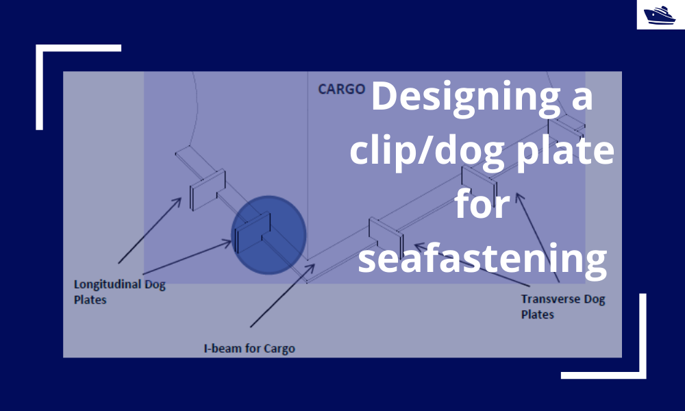
Designing a clip/dog plate for seafastening
Introduction In an earlier article, we saw how to design stoppers for seafastening. Stoppers are items that are used to contain the translation movements (longitudinal and transverse directions) of a cargo on the deck/hold of a vessel. That brings us to the question –...
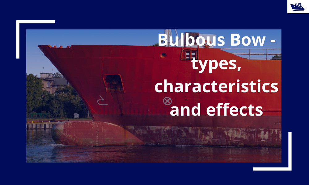
The Bulbous Bow – types, characteristics, and effects
This is Part 2 of the two-part series on Bulbous Bows. For Part 1, click here By Tamal Mukherjee, *This article originally appeared in May 2019 edition of Marine Engineers Review (India), the Journal of Institute of Marine Engineers India. It is being...
Marine Propeller and Shafting Alignment – Part 2
Gap & Sag Alignment Gap and Sag Alignment is carried out to bring the engine to its final position, in case of directly coupled installations, and to bring the gear box to its final position in case of installations with reduction boxes. The figure below indicates...

Why you made reference for the DAF to the documents of DNV (not DNVGL since about one month) almost all clasification society has its own ampric formula to calculate the vertical acceleration considering ship particulars.
Hi Kemal
Thanks for your comment. Indeed, all Class societies have their own empirical formulae, and you can very well use them. We referred to DNV as theirs is one of the more widely used formulae.
Thanks for your comment, and I hope you benefit more from our platform.
Regards
Team TheNavalArch