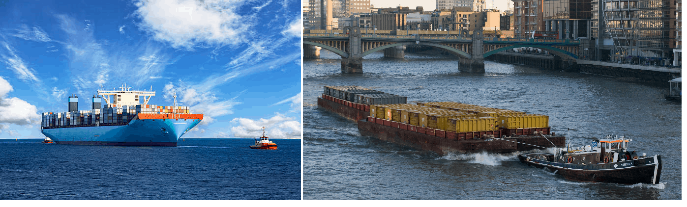
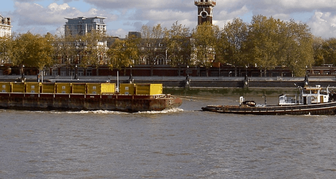
Barges are the simplest, and yet most widely used of marine vehicles. They are used for a variety of purposes ranging from carrying cargo in bulk or liquid, to even carrying passengers for short inland cruises. Barges are mostly towed by another barge called a tug, but some barges can also be self-propelled. Barges are also mostly used on inland waterway routes and lakes/rivers, but many offshore barges are used for long-distance open-ocean transportation also.
Barges are flat-bottomed, and box-shaped, which makes their design and construction quite simplified.
Knowing the trim and stability of a Barge during operation is an important input to successful operation/voyage of the Barge. Stability would mean that the barge should have sufficient righting moment to bring it back to an upright position in case of heeling.
IMO Criteria for Stability
The International Maritime Organization (IMO) is the international statutory authority which has laid out the criteria for Stability to be met by all barges, including Barges. These are contained in its document ‘IMO 2008 Intact Stability (IS) Code’. Basically, the Stability criteria are parameters which are calculated on the righting arm curve of the barge (also called the GZ Curve), and IMO requires these parameters to meet certain minimum requirements. The IS Code lays out the stability criteria for all types of barges, and it also provides specific criteria applicable to non-self-propelled Barges (or pontoons) carrying deck cargo.
In this article, we’ll explore the Stability requirements Barges, including that of a special type of Barge which is non-self-propelled and carries deck cargo. Such Barges are called ‘Pontoons’.
How to decide which criteria to apply?
To decide which criteria to apply, it is important to know the type of Barge. If it is a pontoon, as defined in Part B, Ch2, Sec 2.2.1 of IS Code 2008, then the pontoon stability criteria apply. The definition of a Pontoon is shown in the picture below:
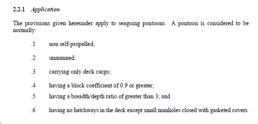
Definition of Pontoon [2]
The Stability criteria to be met by the GZ curve of a pontoon are in Sec 2.2.4 shown below:
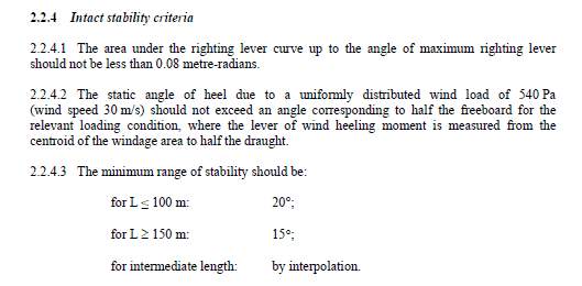
Pontoon Stability Criteria [2]
If the barge doesn’t satisfy the definition of Pontoon as above, then the general Stability criteria as in Part A, Ch 2, Sec 2.2 of IS Code 2008 shall apply. The general criteria are shown below:
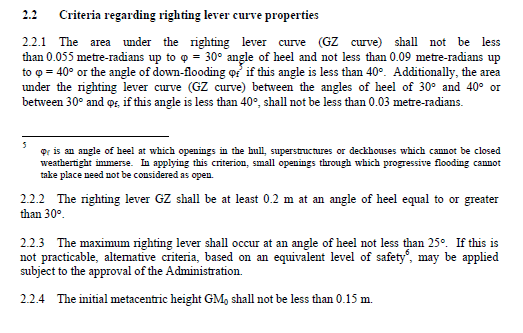
General Stability Criteria applicable to all vessels [2]
Further, if the Barge is meant for some specialized operation (e.g., Crane Barge or Jack-up barge), then special criteria applicable to these types of barges will apply. In this article we will limit ourselves to deck cargo barges and pontoons.
Stability Calculation for an existing Barge
If you have an existing barge for which the following documents are available, then the Stability calculation can be done using an excel-based interface, some formula and programming using the VBA developer interface of Excel.
Documents required
- Hydrostatic particulars and cross curve data of the barge
- Capacity Plan – showing the geometry of tanks and their capacity
- Tank Tables – showing filling of tanks at different levels
- General Arrangement
- Location of downflooding points (Read about downflooding points here)
Methodology
Now we will talk a bit about the methodology behind the computation, by using a reverse thinking process.
The objective of the whole exercise if to find out the following:
- The trim and hydrostatics of the floating condition
- Stability – righting arm curve
Trim and Hydrostatics of Floating Condition
The trim and hydrostats at a floating condition is dictated by the total weight and the position of the Center of Gravity at that floating condition. The total weight will comprise the self-weight of the barge (lightweight), the weight of provisions, crew (if any), the weight in tanks, and deck cargo (if any). All these inputs can be taken from the user in a tabular format. Next, we need to get the trim/hydrostatics of the floating condition. For this, let’s understand what hydrostatics mean – the hydrostatic properties of the floating condition are those properties which change with a change in the loading. For example, the draft of the barge changes with changing loading and is a hydrostatic property. Similarly, the center of buoyancy of the barge changes with the changing loading, and so it is another hydrostatic property. Here we list down the common hydrostatic properties that are used to assess a floating condition:
| Final Hydrostats | |
| Displacement | Determined by the total weight of the barge |
| Mean Draft | The level at which the barge floats |
| LCB | The longitudinal center of buoyancy |
| VCB | The vertical center of buoyancy |
| TPcm | The Tons Per cm of immersion – weight required to immerse the barge by 1 m |
| LCF | The longitudinal center of floatation |
| MCTcm | Moment to change trim by 1 cm |
| KMl | The metacentric radius (longitudinal) |
| KMt | The metacentric radius (transverse) |
| Total Trim | The difference between drafts of aft and fwd ends |
| KG | The vertical center of gravity |
| FSM Correction | Free Surface Moment in tanks (leads to correction in KG) |
| KG(corrected) | Vertical center of gravity corrected for FSM |
| GM(transverse) | The metacentric height (KM-KGcorrected) – transverse |
| GM(long) | The metacentric height (KM-KGcorrected) – longitudinal |
| Heel | The heel of the barge in equilibrium position |
The above parameters are unique to a specific loading condition of a barge. How can hydrostatics be calculated? The steps are listed below:
- Calculate the total weight (W) of the barge in the floating condition – this includes lightweight plus deadweight (weight in tanks + weight of crew/provisions + deck cargo)
- Calculate the vertical center of gravity of the barge (KG) measured from the keel (or any other reference point) in the floating condition
- Check the hydrostatic table of the barge, and find out the two rows whose displacement values are just higher than and just less than W.
- Interpolate between the two rows to find out the value of draft, KM, LCB, VCB, TPcm, MCTcm
- Calculate the FSM effect from the level of filling in tanks, and from the standard formula for FSM
FSM effect for a tank = (Tank density/Sea Water Density) x (Transverse Moment of Inertia of a tank/Barge’s Displacement)
FSM effect for all tanks is them summed up to give the net effect on the KG of the barge (it raises KG). The corrected KG is given by KGcorrected = KG + FSM effect
- The metacentric height (GM) can be calculated from the formula
GM = KM – KGcorrected
- Heel: equilibrium Heel can be obtained by calculating the transverse Center of Gravity of the barge in the loading condition. From the transverse Center of Gravity, the transverse heeling moment on the barge can be calculated. The heeling moment curve can be superimposed on the righting arm curve to give the heel as their intersection point.
The righting arm curve and Stability
Once hydrostats have been calculated, the next exercise aims at finding the righting arm curve of the barge for a given loading condition, with a specific configuration of tanks. Basically, the righting arm curve is calculated from a formula as below:
GZ = KN – KG sinθ
Here, GZ = righting arm, KN = the lever arm obtained from cross curves (also called KN curves). KG is the vertical center of gravity of the barge in the loading condition, measured from a reference point K (K is generally taken as the baseline of the barge). The whole concept is shown in the figure below:
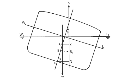
GZ calculation from KN [3]
Thus, the three parameters which are needed for getting the GZ curve are:
- Cross curve, KN. These can be obtained from the cross-curve table of the barge which is generally available in the stability booklet of the barge. These are plotted vs the displacement of the barge, and for different angles of heel, and look like below:
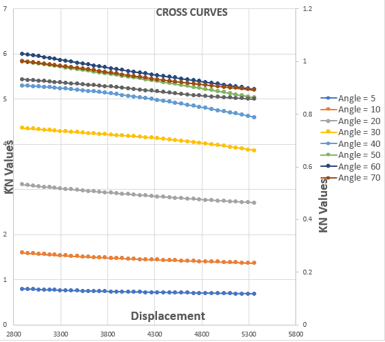
Stability Cross Curves
- The vertical center of gravity (KG) above the baseline – this is calculated from the total loading of the barge – including its lightweight, tank weights, weight of provisions/crew and deck cargo weight (if any)
- The angle of heel (θ)
To plot the GZ curve for a given loading condition, we will need to know the KN values for different angles of heel for that loading condition. For doing this, we calculate the displacement of the loading condition and use the cross curves chart/table to get the KN values. We can see it demonstrated from the graph below
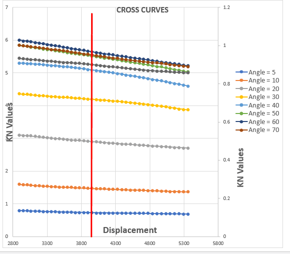
Getting KN values at displacement 4000 MT
Once we have the values of KG, and KN for different angles of heel, we can calculate the values of GZ for different heel angles in a tabular form to generate the GZ curve
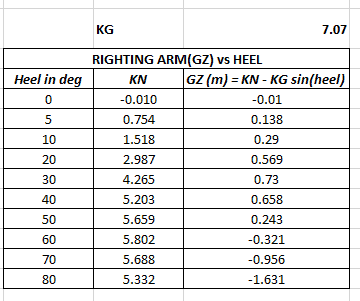
GZ calculation from KN
The resulting GZ curve will look like the below:
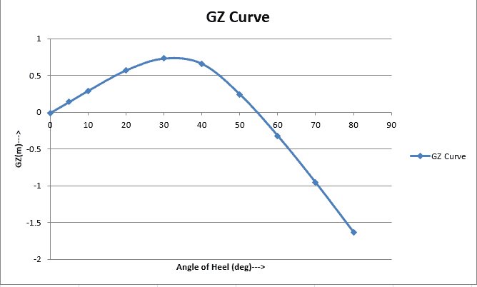
Righting Arm (GZ) Curve vs Heel
Evaluating Stability parameters as per IMO A.749(18)
Next, we need to calculate how the GZ curve fares on the Stability parameters.
Case 1: for Barges which are not Pontoons
For these Barges, the IMO general criteria will apply
| Sl.No. | Parameter | Method of calculation |
|
1 |
The area under the righting lever curve (GZ curve) should not be less than 0.055 metre-radians up to 30° angle of heel.
|
By numerical integration of the GZ curve |
|
2
|
The area under the righting lever curve (GZ curve) should not be less than 0.09 metreradians up to 40° angle of heel or the angle of downflooding if this is less than 40°.
|
By numerical integration of the GZ curve |
|
3 |
The area under the righting curve between the angles of heel of 30° and 40° or between 30° and the angle of downflooding if this angle is less than 40°, should not be less than 0.03 metre-radians. | By a difference of areas in Criteria 1 & 2 |
|
4 |
The righting lever GZ should be at least 0.20 m at an angle of heel equal to or greater than 30°. | Directly from the GZ curve, by measuring the value at 30 degrees |
|
5 |
The maximum righting arm should occur at an angle of heel preferably exceeding 30° but not less than 25°.
|
By finding the maximum of the GZ curve |
| 6 | The initial metacentric height GMo should not be less than 0.15 m. | From hydrostats table |
Case 2: for Barges which are Pontoons
For these Barges, the specific Pontoon Criteria will apply
| Sl.No. | Parameter | Method of calculation |
|
1 |
The area under the righting lever curve (GZ curve) upto maximum GZ should not be less than 0.08 m-rad
|
By numerical integration of the GZ curve |
|
2
|
The static angle of heel due to a wind of speed 30 m/s should not exceed an angle corresponding to half freeboard
|
By calculating the angle of heel by superimposing wind heeling moment on GZ curve, and calculating the freeboard from the hydrostats |
|
3 |
Minimum range of Stability should be 20 degrees for Length of pontoon <= 100 m, and 15 degrees for Length of pontoon >= 150 m, and by interpolation in between | By calculating the angle of heel at which GZ becomes zero (other than the equilibrium angle) |
IMO Weather Criteria
Similar to the standard stability criteria listed above, there’s also IMO Weather criteria for barges. These are applicable for barges which are not pontoons, and for which the general IMO Stability Criteria apply. These are shown below:
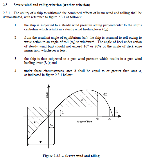
IMO Weather Criteria
For calculating the IMO weather criteria, we need to calculate the heeling moment which a barge experience due to a wind from transverse direction. The heeling moment is divided by the displacement of the barge in the loading condition to give the heeling arm. This heeling arm is plotted on the GZ curve to evaluate the stability parameters for the weather criteria. This is shown in the figure below:
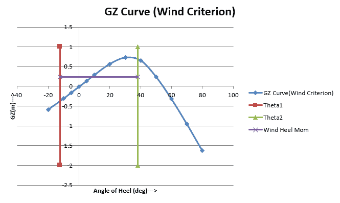
GZ Curve for Weather Criteria
The whole process can be put into multiple steps:
- Get the user to input vessel’s basic geometry, lightweight, hydrostatics and cross curve data in tables
- Get the user to input tank geometry (tank tables)
- Get other information like downflooding points in tabular format
- Prepare a spreadsheet for a typical loading condition in which the user can change the tank filling, and add any deck cargo
- Evaluate the hydrostats of the loading condition
- Use the hydrostats to get KN values for the loading condition
- Generate the GZ curve using KN values
- Calculate the Stability parameters from the GZ curve
The steps 1 to 8 above can be put in the form of an MS Excel workbook with a separate worksheet for each step. With some excel VBA programming in the background, the workbook can be used to create a custom Stability calculator for a vessel and can be used to determine the loading and stability of the vessel every time a new voyage/operation is to be undertaken.
That brings us to the end of this article. If the data of an existing barge is available, then the Hydrostatics and Stability of the barge can be evaluated by following the basic formulations of Stability.
Please do take some time to explore TheNavalArch’s Stability Suite: three products that are used for three different barge types.
- ShipStab – is for all cargo barges which are covered under the IMO general criteria in Part A, Ch 2, Sec 2.2 of IS Code 2008
- PassStab – is for Passenger barges, which have additional criteria in Part A, Ch 3, Sec 3.1 of IS Code 2008
- PontoonStab – is for all pontoons which are covered in Part B, Ch 2, Sec 2.2 of IS Code 2008. Due to be launched on 9th July, 2020
References:
[1] Principles of Naval Architecture, Edward V. Louis, Ch II
[2] IMO Res A.749(18)
[3] Barge Stability for Masters and Mates, By Bryan Barrass, Capt D R Derrett
Disclaimer: This post is not meant to be authoritative writing on the topic presented. thenavalarch bears no responsibility for the accuracy of this article, or for any incidents/losses arising due to the use of the information in this article in any operation. It is recommended to seek professional advice before executing any activity which draws on information mentioned in this post. All the figures, drawings, and pictures are property of thenavalarch except where indicated, and may not be copied or distributed without permission.
Why the bollard pull calculation method for a barge won’t work for a ship
In my working with the marine transportation industry for more than a decade now, I have come across many different calculations for required bollard pull for both barges and ships. The principles of the calculation are same, whether it is a ship, a barge...
STEEL COILS LOADING – ITS CHALLENGES AND WAYS TO OVERCOME
STEEL COILS LOADING – ITS CHALLENGES AND WAYS TO OVERCOME by Mr. Spiros Malliaroudakis (Founder & Managing Director, S.A. Malliaroudakis Maritime (UK) Ltd) The loads derived from steel coils loading are very concentrated, leading to higher stresses...
Naval architecture, new challenges and a new horizon
Naval architecture, new challenges and a new horizon by Lim Soon Heng, BE, PE, FSSS, FIMarEST Founder President, Society of FLOATING SOLUTIONS (Singapore) Civilization has arrived at a point of inflexion triggered by global warming and rising sea levels....
Mooring System Design and Analysis
Mooring System Design and Analysis by Rahul Kanotra, Consultant Naval Architect As the offshore industry moves towards greater technological advancements, one thing that has plagued the engineers is the “plug and play” computer programs or software. I am not against...
Cargo Stoppers – why they are critical and how to design them
Stoppers and their critical role in seafastening of cargo Introduction A cargo transported on the deck of a ship is subject to many forces. These forces comprise of the inertial forces due to the ship motions – the three translations and three rotations – and the...
Are you chartering a tug bigger than necessary for your Barge?
Barges are one of the most frequently used means for transporting deck cargo of different shape, size and weight. While some barges are self-propelled, the majority is towed by another vessel called a ‘Tug’. Once an owner or charterer...
Fendering – an Introduction
In this two part article we will talk about Fendering, which is one of the basic but critical operations related to a ship. Fendering is, basically, protecting the ship’s sides from contact with another body (which can be another ship, jetty or quay wall). It can also...
Loadouts – An introduction
Image source: Flickr Loadout Operations - an Introduction Loadout is a term oft heard of in the marine/offshore industry parlance. Loadout is generally referred to the operation of transferring a Cargo or a Structure from the place of fabrication to a sea-borne...
Introduction to Pipe Transportation – Part 3 (Engineering)
Introduction to Pipe Transportation - EngineeringIn Part 1 we learnt about pipes, while in Part 2 we learnt about Planning and Scheduling of pipe transport operations. In this part, we will learn about Engineering.Phase 3 – Engineering.Engineering for pipe...
Introduction to Pipe Transportation – Part 2 (Planning & Scheduling)
In Part 1, we looked at the properties of pipes. In this section, we will be looking at the Planning & Scheduling of a pipe transportation operation (see below, Phase 1 & 2) SECTION 2: PLANNING, SCHEDULING, AND ENGINEERING FOR A PIPE TRANSPORT PROJECT Source:...

I’m an independent Marine Surveyor interested to find information about the Barge’s stability.
Hi Virgilio
Thanks for your interest. You’re welcome to write to us at info@thenavalarch.com
I am a marine manager, interested to create a stability calculation spreadsheet for our small company in Papus New Guinea.
Please check your email
Hi
I have a case where I need to calculate the stability for a barge, could I get a copy of your excel sheet?
Hi Eric
Thanks for your query. At the moment it is not available for trial. You can watch the video to see how the software works. If you have any questions please send to info@thenavalarch.com
Hi, could I get a copy of your excel sheet please?
Hi
Thanks for your query. At the moment it is not available for trial. You can watch the video to see how the software works. If you have any questions please send to info@thenavalarch.com
Hi, could I also get a copy of your excel sheet please? Thanks in advance.
Hi
Thanks for your query. At the moment it is not available for trial. You can watch the video to see how the software works. If you have any questions please send to info@thenavalarch.com
Hi,
May I request to have a copy of the excel sheet please? Currently working on barge and pontoons and would be good to have this kind of reference just to start with. Many thanks.
Hi Mac
Thanks for your query. At the moment it is not available for trial. You can watch the video to see how the software works. If you have any questions please send to info@thenavalarch.com
Hi ,
I’m work for small transport company in VietNam, some time transport cargo by pontoon.
Could I also get the copy of your excel sheet please ?
Hi Ahmed
Thanks for your query. At the moment it is not available for trial. You can watch the video to see how the software works. If you have any questions please send to info@thenavalarch.com
Hi Minh
Thanks for your query. At the moment it is not available for trial. You can watch the video to see how the software works. If you have any questions please send to info@thenavalarch.com
Hello
Could I also get the copy of your excel sheet please ?
Im working in a building company, and from time to time we need to transport your equipment and materials on barge.
Best regards.
Hi Ahmed
Thanks for your query. At the moment it is not available for trial. You can watch the video to see how the software works. If you have any questions please send to info@thenavalarch.com
Hi ,
I’m work for small transport company in Singapore, some time transport cargo by pontoon.
Could I also get the copy of your excel sheet please ?
Hi Leonard
Thanks for your interest. The excel sheet is available for purchase. You can check it out at https://thenavalarch.com/shipsafe-the-ship-stability-calculator/