by Alessandro La Ferlita, Naval Architect
Ultimate hull girder strength represents the maximum capacity, of the hull girder beyond the structure fails.
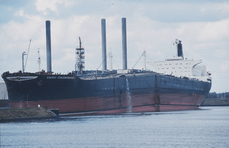
In fact, if the vertical bending moment applied overcomes a certain maximum value, the ship can collapse (Figure 1) due to different phenomena as buckling and progressive collapse [1] of the compressed part.
Instances are famous cases of the oil tanker “Energy Concentration” that happened in 1980 and the container vessel “MOL COMFORT” in 2013.
Figure 1 Collapse of “Energy Concentration” [2]
The estimation of the ultimate strength plays an important role in structural safety and for reliability in terms of loads during the life of the vessel.
In general, the ultimate hull girder capacity considers the evaluation of the overall strength by summing up the general load capacities of individual elements such as plates, stiffeners, girders within the cross-section.
Methods for determining the ULS
Several rule models can be used for calculating the ultimate strength.
1) Smith method (Iterative approach)
2) ISUM (Idealized Structural Unit Method)
3) Non-linear FEA.
The first method is quite well known and prescribed by IACS.
The original idea comes from Smith at the end of 70’s which developed a simplified method to evaluate the ultimate strength basing his approach on the following assumptions [3]:
- the section of the ship to take into account is between two stiffened frameworks and consists of all the structural elements that contribute to longitudinal strength
- the collapse section remains plane when the curvature tends to increase or decrease;
- the behavior of the material constituting the resistant section is ideal elastic-plastic characterized by the load end shortening curve;
- the structural section is considered to consist of j elements (j → discrete number of elements) whose structural behavior is independent when the curvature is acting on the section.
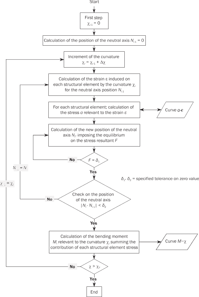
The main steps (Figure 3) to consider for the procedure are the following [3] [4]:
- subdivision of the main cross-section in a defined type of element correspondingly into:
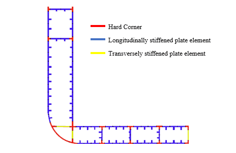
- Hard corner Element, which is generally constituted by two plates that do not lie in the same plane: one is horizontal and the other is vertical.
- Longitudinally stiffened plate element, with attached plating up to the midpoint between adjacent stiffeners on each side.
- Transversely stiffened plate elements, which are typical geometrical areas between stiffener elements and hard corner elements (Figure 2).
Figure 2 Subdivision – Hard Corner/Transversally stiffened Plate Elements/ Longitudinally stiffened plate element
Figure 3 Description of the Smith Method [3]
2. The stress-strain relationships of individual elements are carefully considered and obtained, taking into account: the influences of yielding, buckling, and the initial Neutral axis.
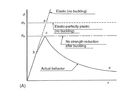
Regarding this second step, the stress properties of each element are defined using different curves that describe the relationship between the axial load and displacement. In general, it is possible to distinguish them according to their behavior (figure 4a) [5]:
(a) elastic without buckling;
(b) elastic-perfectly plastic without buckling;
(c) buckling/yielding without strength reduction beyond the ultimate strength;
(d) buckling/yielding with strength reduction beyond the ultimate strength.
This last behavior is quite realistic and its capacity decreases after its maximum value has been obtained.
In general, those curves could be determined by using empirical approaches or by nonlinear finite element method, using for example some software as ANSYS or ABAQUS. Nevertheless, direct methods are given by DNV GL which suggests using a specific formula for obtaining the corresponding stresses as shown in table 1.
Element Mode of failure Lengthened stiffened plate element or stiffener element Elasto-plastic collapse Shortened stiffener element
Beam column buckling
Torsional buckling
Web local buckling of flanged profiles
Web local buckling of flat bars
Shortened stiffened plate element Plate buckling
3. Forces are derived by multiplying the stress by the area of the element considered. The final sum of the forces above the neutral axis should be equal to the sum of the forces below the neutral axis; If this condition is not satisfied, it means that the initial position is shifted and a new one should be searched;
4. Verification that the new neutral axis (which guarantees the equilibrium of stresses) differs with a low tolerance value in respect to that one assumed at begin of the procedure. If this condition is not fulfilled, it is necessary to reiterate all the process basing the calculation on the last neutral Axis obtained;
5. In case the previous step is satisfied, it is possible to calculate the bending moment. After that, it would be necessary to increase the curvature of a certain delta of increment;
Residual ULS
The determination of the ULS plays an important role especially when the ship results damaged and the salvage operation is needed.
In fact, grounding or collision can lead to a reduction in the effectiveness of the structural elements and consequently to the reduction of ultimate strength.
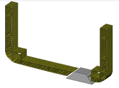
Figure 4 Damage due to grounding [5]
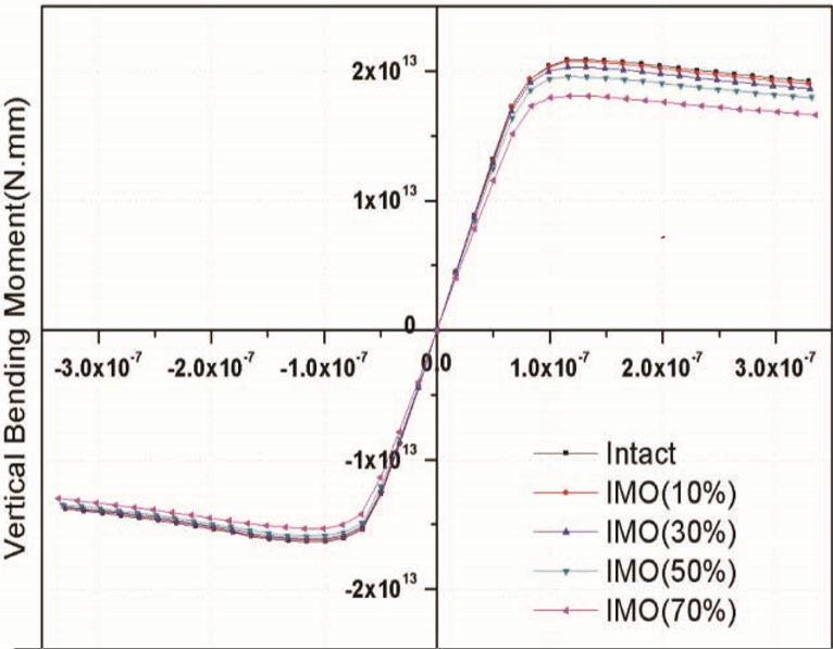
In such circumstances, by neglecting the elements which belong to the cross-section (Figure 4) which do not carry anymore the longitudinal strength, it is possible to calculate the ULS (Figure 5).
In this context, the methods before mentioned could be applied, but paying attention to the symmetry/asymmetry of the damage
Figure 5 Residual ULS for different damaged scenario vs Intact ULSS [6]
RD Diagram
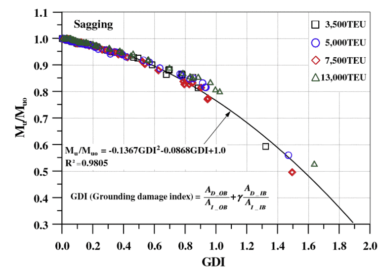
Paik et al. [5] proposed an innovative method for assessing the safety of a ship which has suffered damage grounding through the application of R-D (Residual Damage) Diagram.
Figure 6 Residual damage diagram [7]
They are obtained in the following way.
First of all, the characteristics of the ships, including geometry, dimensions, and material properties are defined. Then a limited number of probable damage scenarios representing all possible scenarios can be selected by a
probabilistic approach.
In practice, it means that a small number of probable scenarios for possible accidental or in-service damage are selected using for instance a sampling technique in which the random variables affecting the damage are probabilistically characterized.
Afterward, the GDI (grounding damage index) is defined for describing the damage severity for each of the considered scenarios.
The residual strength of the ships in the grounding damage scenarios is then calculated by using a simplified approach or by applying more complex methods, such as non-linear FEM (Finite Element Method).
Finally, the R–D diagram is established based on these calculations performed.
Furthermore, the GDI concept can be applied to determine the acceptance criteria for grounding strength performance [9].
For example, IMO (International Maritime Organization) specifies requirements that the ultimate longitudinal strength of all newly built ships be no smaller than 90% of the strength performance.
In general, those kinds of diagrams will be very useful for a first-cut assessment, immediately after it has been suffered a grounding, by knowing the damaged area.
Bibliography
|
[1] |
Ö. E. Bayraktarkatalb, “Effects of Key Factors on Hull Girder Ultimate Strength Estimation by Progressive Collapse Calculations,” Latin American Journal of Solids and Structures, pp. 2371-2392, 2016. |
|
[2] |
“www.shipspotting.com,” [Online]. Available: http://www.shipspotting.com/gallery/photo.php?lid=1688178. |
|
[3] |
DNVGL-CG-0128, “APPENDIX E HULL GIRDER ULTIMATE BENDING CAPACITY BY MULTI-STEP METHOD,” 2018, pp. 125-136. |
|
[4] |
Soares, A. W. Hussein & C. Guedes, Design Equation for the Ultimate Capacity of Double Hull Tankers Designed According to the Common Structural Rules, Lisboa, Portugal: Centre for Marine Technology and Engineering (CENTEC), Technical University of Lisbon, 2008. |
|
[5] |
M. F. Tetsuya Yao, “PROGRESSIVE COLLAPSE BEHAVIOR OF HULL GIRDER UNDER,” in Buckling and Ultimate Strength of Ship and Ship-like Floating Structures, Kidlington, Oxford, United Kingdom : Butterworth-Heinemann is an imprint of Elsevier Á, 2016, pp. 321 – 336 – 348 – 353. |
|
[6] |
DNVGL-CG-0128, “APPENDIX E HULL GIRDER ULTIMATE BENDING CAPACITY BY MULTI-STEP METHOD,” DNVGL-CG-0128, 2018, pp. 125-136. |
|
[7] |
J. K. Paik,D. K. Kim,P. T.Pedersen,H. Kim , “DEVELOPMENT OF A RELATIONSHIP BETWEEN RESIDUAL ULTIMATE LONGITUDINAL STRENGTH VERSUS GROUNDING DAMAGE INDEX DIAGRAM FOR CONTAINER SHIPS,” Proceedings of the ASME 31st International Conference on Ocean, Offshore and Arctic Engineering OMAE, vol. 2, pp. 1-10, 2012. |
|
[8] |
Ji-Myung Nam and Joonmo Choung , “Residual Longitudinal Strength of a VLCC Considering Probabilistic Damage Extents,” Proceedings of the Twenty-second (2012) International Offshore and Polar Engineering Conference , 2012. |
|
[9] |
Do Kyun Kim, Preben Terndrup Pedersen, Jeom Kee, “Safety guidelines of ultimate hull girder strength for grounded container ships,” Safety Science, vol. 59, pp. 46-54, 2013. |
Please do checkout TheNavalArch’s simple-to-use and effective calculator for Hull Ultimate Strength – called the Hull Grounding Damage Index (GDI) calculator
Disclaimer:
The views, information, or opinions expressed are solely those of the author and do not necessarily represent those of TheNavalArch Pte Ltd and its employees
Alessandro La Ferlita
Naval Architect & Marine Engineer
Naval Architect and Marine Engineer
TheNavalArch Interview Series: Mr. Balakrishna Menon
Mr. Balakrishna MenonEngineering Director Mooreast (Asia) Pte Ltd TheNavalArch's Interview Series is an endeavor to get insights from the best engineering and business brains in the industry, and present them to its users for the larger...

Floating Rice Fields, the quest for solutions to combat drought floods and rising sea levels
by Lim Soon Heng, BE, PE, FSSS, FIMarEST Founder President, Society of FLOATING SOLUTIONS (Singapore) Abstract Amazing as it seems, there is a case for growing rice on floating platforms in the sea. The capital expenditure to develop this is offset by the opportunity...

CAPSIZE OF LIFTBOAT IN TRANSIT
This paper was originally presented in the 27th Offshore Symposium, February 22nd, 2022, Houston, Texas Texas Section of the Society of Naval Architects and Marine Engineers It has been reproduced here for the readers of TheNavalarch INTRODUCTION In 1989 a Class 105...
Designing a closed chock as per IACS rules
Introduction Chocks are used universally for mooring and towing operations on ships. For towing operations, Chocks are used for guiding the towing rope from the winch through the outer shell of the vessel to the tug. For mooring operations, the chock is used to...
The Optim22 method of hull optimization – Part 2
This is a follow-up article to the previous article on Framed Structures Optimization. 1.1 Abstract A previous article introduced the Optim22 method. This one adds additional background information plus 3 more case studies to...
The Optim22 Method of Weight Optimization of Framed Steel Structures
1 Abstract A semi-automated structural weight optimization system is presented for framed structures of post and beam construction which is based on basic structural member design principles. The approach is to adjust member properties in a manner that...

Combating rising seas with floating structures
Introduction Rising sea level is an existential threat for many coastal cities. The sea is rising subtly but relentlessly at an exponential rate. Many predictions of how high and how fast it will rise in the next 50 years have proved to be understated. According to...
Sea Pressure Loads Calculation based on DNV Rules
Introduction Sea pressure loads are an important factor in the structural design of a vessel. What is sea pressure load? As the term suggests, it is the external pressure on the vessel due to the surrounding sea. What kind of pressure it is, and how to...
A quick empirical method for resistance estimation of planing vessels
Resistance estimation for a vessel is a fundamental exercise in design of the vessel. Resistance is a property that depends on the vessel’s shape and form. A conventional ship-shaped vessel with a bulb will have completely different resistance characteristics compared...

Powering the maritime industry with Hydrogen – Part 2
Powering the shipping industry with hydrogen - Part 2: Hydrogen propulsion on a ship - opportunities and challenges Introduction In the Part 1 of this article, we explored the basic properties of Hydrogen as a fuel, and also the opportunities and challenges...

