Introduction
In an earlier article, we saw how to design stoppers for seafastening. Stoppers are items that are used to contain the translation movements (longitudinal and transverse directions) of a cargo on the deck/hold of a vessel.
That brings us to the question – what about tipping of the cargo? If the cargo is subjected to external forces that cause it to tip, how do we protect the cargo against tipping?
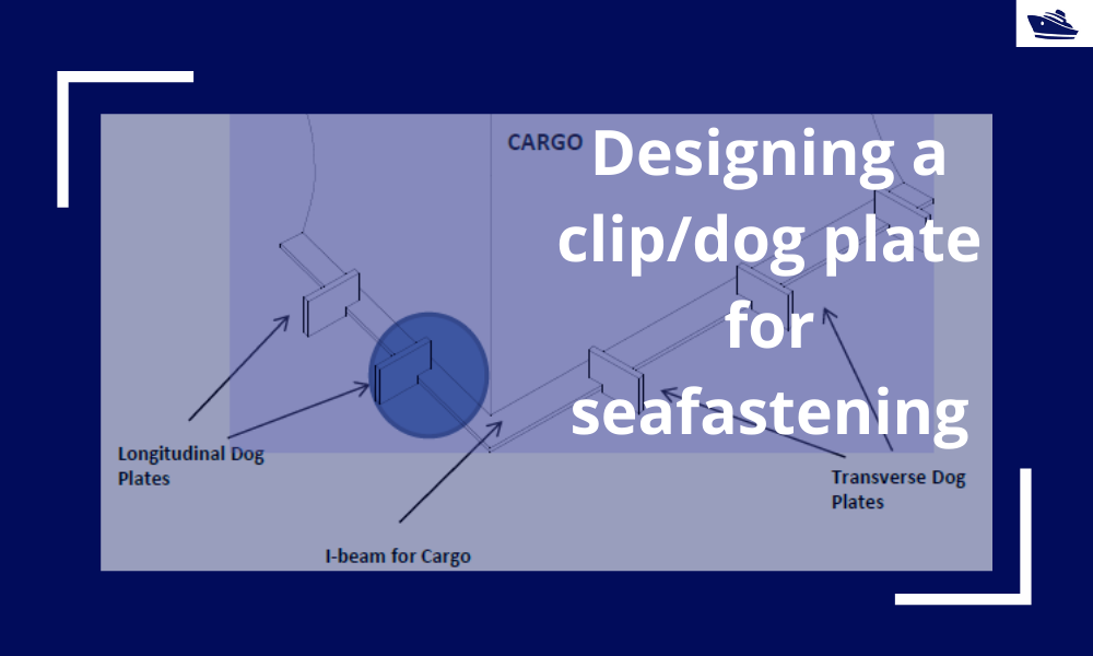
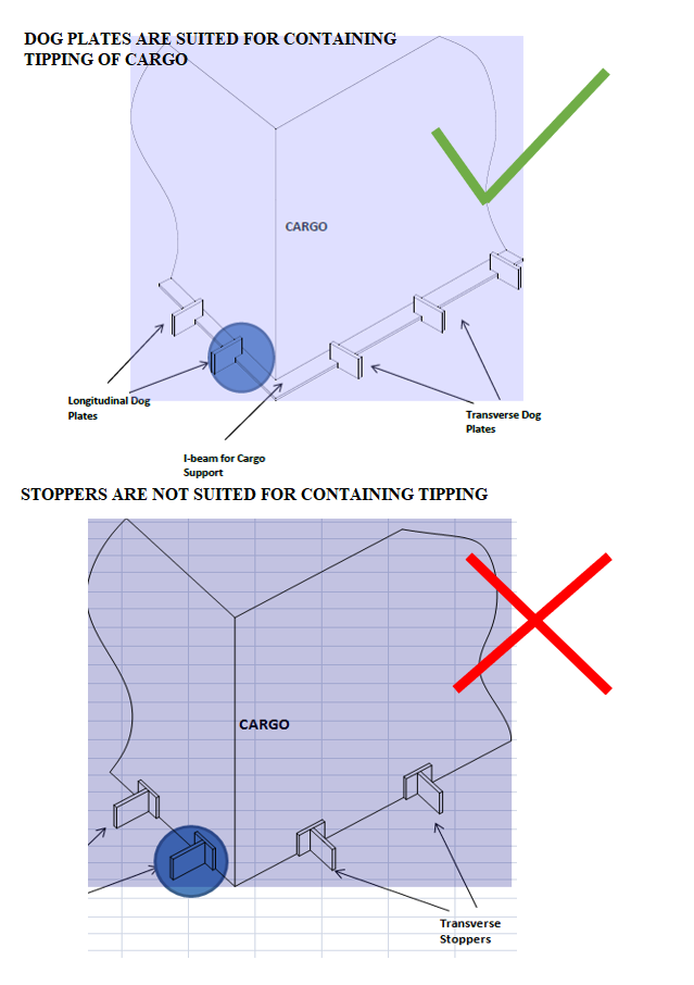
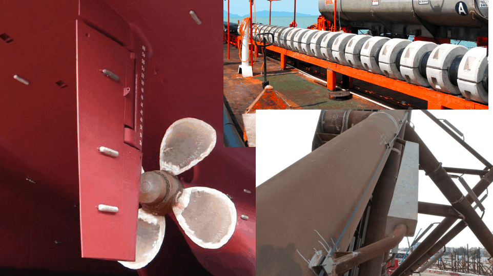
Thinking in basic terms, to prevent cargo from tipping/overturning, we will need something that pins or clips it to the deck. Such a seafastening item is called a ‘Clip’ or a ‘Dog Plate’. Imagining such an item, it can be an ‘L-shaped’ structure that clings on to the base of the cargo. If we see the figure below, the dog plate is like a jaw that clamps down on the base frame of the cargo. We can also see that this kind of structure will help prevent the overturning of the cargo, as compared to stoppers which can prevent only translation. At times, both dog plates and stoppers may be used together on the same cargo with dog plates resisting overturning and stoppers resisting translation.
Designing a Dog Plate:
In this section, we’ll see how do we go about designing a dog plate for a particular operation.
Any design takes up the following flow:
- Evaluate the forces acting on the structure
- Check the stresses on the structure due to the forces
- Iterate the design until the stresses are within the acceptable levels
Forces on the structure:
The cargo on the vessel will experience forces in the three directions – longitudinal, transverse, and vertical (uplift), besides the self-weight of the cargo. The first three forces depend on the environment in which the vessel is operating, and one simple but conservative way of calculating these forces is to follow DNVGL guidelines (See DNVGL-ST-N001, also see our product on Cargo Forces and Accelerations)
Longitudinal or Transverse Forces
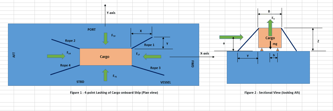
In the figure below that shows the plan of a vessel’s deck carrying cargo, we can see that there are multiple dog plates in each direction to resist the respective force (transverse or longitudinal).
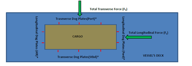
If the number of dog plates in the transverse direction is nT and the total transverse force on the cargo is FT, then the transverse force on a single dog plate in the transverse direction is
FT1 = FT/nT
Similarly, in the longitudinal direction, the total longitudinal force divided by the total number of dog plates in that direction gives the force on one dog plate.
Uplift Force
The uplift force is a vertically upward force due to the cargo motion. It is calculated from a motion analysis or from empirical relations (See our product for Cargo Forces and Accelerations).
Self-Weight of Cargo
The cargo also experiences its own self-weight that acts vertically downwards.
The force diagram of the Cargo can be drawn as below:
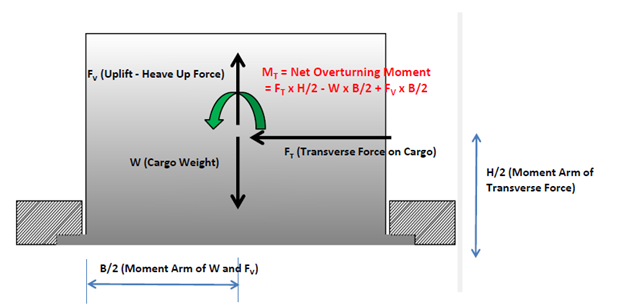
We can see that given the location of the dog plate, the following forces and moments will be experienced by it:
- The transverse force FT will be borne by all the dog plates.
- An overturning moment on the whole cargo, MT, due to FT, Uplift Force, and Self-Weight will also be borne by all dog plates. We can see that while FT and FV will cause the cargo to tip, the restoring moment due to self-weight protects it from tipping.
MT = FT x H/2 – W x B/2 + FV x B/2
The above force and moment can be divided by the number of dog plates (nT in the transverse direction) to give the force and moment per dog plate.
FT1 = FT/nT
MT1 = MT/nT
Translation of forces to the Dog Plate
The net overturning moment MT1 on a single dog plate translates effectively to an uplift force on the dog plate due to the moment. Considering the uplift force to be acting at the dog plates on either side, the effective uplift force on each dog plate is
FV1 = MT1/B
where B is the width of the cargo.
Next, we see the force diagram of the Dog Plate itself:
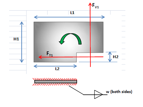
We can see that the following forces are acting on the dog plate:
- The translation force FT1, which gets directly translated from the cargo
- The uplift force FV1, which occurs due to the overturning moment
Stresses on the dog plate
The above two forces lead to various stresses for which the dog plate needs to be analyzed:
- Shear Stress: The force FT1 leads to shear stress on the dog plate
- Tensile stress: The effective tensile force is calculated from the moment of the two forces FT1 and FV1 about the base, divided by the length of the base, L2.
- Bending Stress: bending moment at the base is calculated by adding the bending moments due to FT1 and FV1 at the base.
- Weld Check: The weld of the dog plate to the deck also needs to be checked similarly for shear, tensile and bending stresses
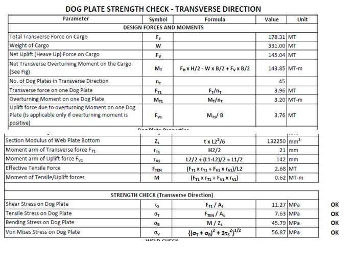
By calculating the forces and moments applicable, the stresses can be calculated, and the suitability of the dog plate evaluated. Some sample calculations are shown below:
Disclaimer: This post is not meant to be authoritative writing on the topic presented. thenavalarch bears no responsibility for the accuracy of this article, or for any incidents/losses arising due to the use of the information in this article in any operation. It is recommended to seek professional advice before executing any activity which draws on information mentioned in this post. All the figures, drawings, and pictures are property of thenavalarch except where indicated, and may not be copied or distributed without permission.
Vessel with Stern on Quay: A simplified method for mooring design
A vessel at berth experiences much lower forces compared to a vessel in the open sea due to the milder environment, but it still requires a mooring configuration suitable to the forces it experiences, and also suitable for the type of berthing configuration adopted....
Cathodic Protection – Ships, Offshore Platforms, FPSO’s and Pipelines: a comparison
Cathodic protection of a structure is an exercise which requires close study of the structure on which it is going to be implemented. The type and quantity of cathodic protection by anodes will depend upon multiple factors: the Geometry of the Structure, the...
Role of a naval architect – a walkthrough (Part – 1)
This is the first in a series of articles on 'Role of a Naval Architect' by Mr Bijit Sarkar, a Naval Architect with 35+ years of experience in ship design and shipbuilding. I would define a naval architect as one who has the ability to greet the client as he/she walks...
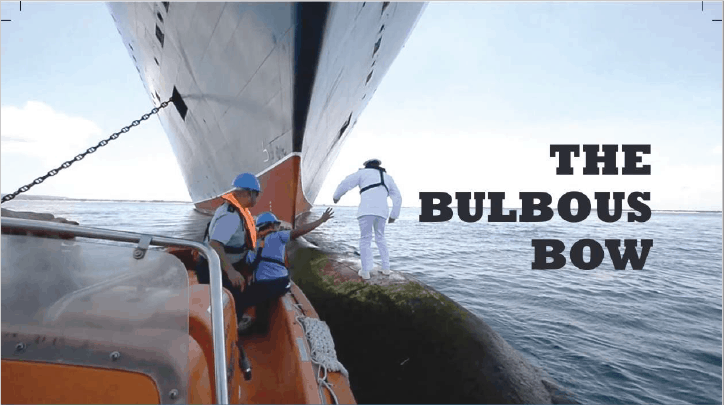
The bulbous bow – why some ships have it and others don’t
By Tamal Mukherjee, This is the Part 1 of a two part article on the Bulbous Bow. Part 2 can be accessed here *This article originally appeared in May 2019 edition of Marine Engineers Review (India), the Journal of Institute of Marine Engineers India. It is being...
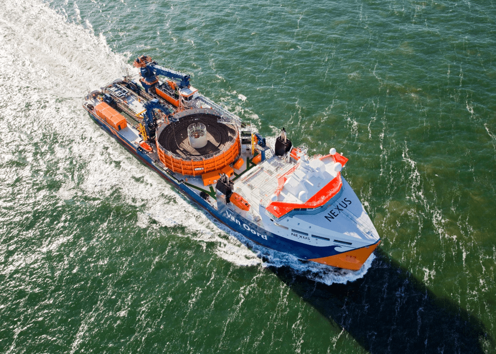
Mitigating risks during subsea cable installation
Over the last 20 years, the interest in offshore wind power generation has increased substantially. Offshore Wind Energy currently provides only 0.3% of world power generation, but the potential is really vast. In the next 20 years the offshore wind industry is set to...
A simple method of selecting the right anchor for mooring a tanker/gas carrier
Anchoring is a fundamental and sensitive operation for a vessel. When a vessel is at anchor, it swings to align itself along the direction of the dominant environment. The anchor is supposed to hold the vessel in varying environmental conditions depending on where the...
Designing a simple 4-point lashing system for a Deck Cargo
Introduction Lashing of a deck cargo on a ship involves different means and mechanisms to secure the cargo to the deck of the ship. This ‘securing’ is important to contain the movement of the cargo in view of the ship motions during the transportation. The simplest...
Calculating a Ship’s Design MBL using OCIMF MEG-4
In Part 1 of this article, we saw a step by step guide to calculate the Environmental forces on a vessel based on “Standard” environmental criteria defined in Section 3 of OCIMF Mooring Equipment Guidelines Fourth Edition (MEG-4) in order to determine the ship’s...
Selecting the right equipment for towing operations – Emergency Towing
In Part 1 of the article, we discussed the regular towing arrangements and how to select the towing gear for the same. In this part, we will discuss the components of the emergency towing arrangement and how to select them. The purpose of emergency towing equipment is...
Preliminary Rigging Arrangement Design OF 4 point, Single Hook Lifts for Non-Specialists
by Michael Harwood, PE, PMP Overview Lifting by crane is a basic construction operation that dates back to at least Sixth Century BC (ancient Greece for example) and the lifting operation itself dates back much further. It is a very common operation in present-day...

Thanks alot for this brief knowledge
NEED FOR PRINCIPLES OF DESIGNING SEAFASTENINGS