
Introduction
GRP laminates are widely used in the fabrication of high-speed crafts and light crafts/boats globally. GRP stands for Glass Reinforced Plastic. As the name suggests, GRP contains glass fibers embedded into a plastic resin. This gives it higher strength, durability, and also a smooth finish [Ref 3].
A laminate used for the fabrication of boats will usually have multiple layers of reinforcements of GRP to achieve the desired strength. In this article, we will learn about a method to calculate the desired number of layers of laminate reinforcements to be used to attain a desired thickness of the laminate. The article follows the formulations provided in the Indian Register of Shipping, Rules and Regulations for the Construction and Classification of High-Speed Crafts and Light Crafts Chapter 7 General Hull Requirements for Fiber Composite and Sandwich Constructions, Section 5 Material Properties and Testing.
CSM vs Woven Roving
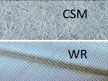
There are two major types of GRPs used in boat fabrication. The first one is CSM, short for Chopped Strand Mat. The CSM has random fiberglass of various lengths dispersed through the resin to provide equal distribution in all directions. Woven Roving, on the other hand, resembles a cloth with woven strands of fibers to form a lattice pattern (see fig below)
CSM vs Woven Roving
Application to FRP boats
FRP, or Fiber Reinforced Plastic boats are made from laminates which have multiple layers of either Woven Roving (WR) or Chopped Strand Mat (CSM), or a combination of the two. The resulting laminate must have the requisite strength and other material properties suitable for its purpose.
How thick the laminate should be? The minimum thickness is provided in the rules of Classification Society to which the boat is classed. Since the laminate is made of multiple layers of reinforcements of CSM or WR, it is important to be able to select the right number of layers of CSM or WR to be able to attain the requisite thickness of the laminate.
Hence, if
- nCSM is the number of layers of CSM with the thickness of each CSM layer being tCSM, and
- nWR is the number of layers of WR with the thickness of each WR layer being tWR, and
- tREQ is the required thickness of the laminate, then
tREQ = nCSM x tCSM + nWR x tWR
Properties of WR and CSM
Since glass is an integral part of the reinforcement layer, the properties like the strength of the laminate are expected to be dependent on the amount of glass reinforcement in the laminate layer.
WR and CSM differ in their mechanical properties owing to the difference in their structure. The tables below demonstrate the difference in their properties
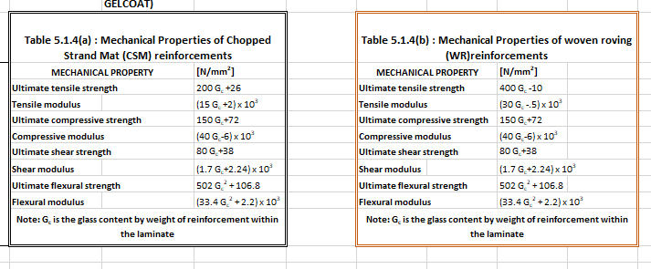
We can note from the tables above that the property GC is central to calculating all the properties of the laminate layer. GC is the Glass Content Ratio by weight of reinforcement within the laminate. Thus the calculation of GC is a pre-requisite to the calculation of the laminate layer’s properties.
Thickness calculation for the laminate
Now we come to the next stage – how to calculate the number of WR or CSM layers needed to achieve a desired thickness?
For this, we will refer to a formula from the Indian Register of Shipping rules [Ref 1]. The formula calculates the thickness of the ith laminate layer from two properties:
- Weight of reinforcement of the layer (expressed in g/m2), Wi
- The Glass Content Ratio, GC, explained above
The formula is shown below:
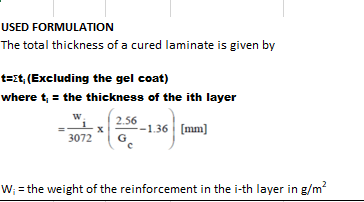
We can see that the total thickness is the sum of the thicknesses of individual layers. The thickness of the ith layer is given by
ti = wi/3072 x (2.56/GC – 1.36), in mm
The layers of the laminate can be made up of WR or CSM or a combination of both. We can achieve a target thickness by trying out different types and numbers of CSM and WR layers, calculating their individual thicknesses and adding them up to check if the minimum thickness (as prescribed by Class rules) is being achieved.
The material properties of each layer can also be calculated using the value of GC for the layer. The material properties of the entire laminate then can be calculated as a thickness-averaged value for all layers.
For example, the ultimate tensile strength (SU) can be calculated thus:
SU = Σ (Sui x ti)/Σ(ti)
Looking at the above calculations, a spreadsheet solution can be set up for performing the calculations in the following steps:
- Step 1 – calculate the required thickness of the laminate from Class Rules
- Step 2 – add multiple rows in a spreadsheet, each row representing a laminate layer which can be either a WR or CSM.
- Step 3 – keep adding rows of laminate layers and calculate their individual properties (thickness and other properties), at the same time calculating the cumulative properties of the laminate.
- Step 4 – The required number of layers is obtained when the target thickness of the laminate is reached
From the steps above, an optimum number of laminate layers required can be obtained. Ending up with a thinner laminate means weaker laminate and thicker laminate means excess material is being spent, and this method can provide the optimum.
TheNavalArch has developed its own app that can be used to calculate the optimum number of layers required for a laminate of requisite thickness. Please do spend some time to check it out
References
- INDIAN REGISTER OF SHIPPING – Rules and Regulations for the Construction and Classification of High Speed Crafts and Light Crafts, Chapter 7 General Hull Requirements for Fibre Composite and Sandwich Constructions, Section 5 Material Properties and Testing
Disclaimer: This post is not meant to be authoritative writing on the topic presented. thenavalarch bears no responsibility for the accuracy of this article, or for any incidents/losses arising due to the use of the information in this article in any operation. It is recommended to seek professional advice before executing any activity which draws on information mentioned in this post. All the figures, drawings, and pictures are property of thenavalarch except where indicated, and may not be copied or distributed without permission.

Marine Propeller Shafting and Shafting Alignment – Part 1
*****This article first appeared in July 2018 edition of Marine Engineers' Review (MER), India. We're reproducing it for the readers of our blog***** Abstract: Since 2013, Shaft Alignment Practice has undergone a change, with developments of Analysis tools. At the...
Using Class Rules to assess the Longitudinal Strength requirement of Barges
Introduction The longitudinal strength of a vessel is integral to its evaluation for a given purpose. To get an introduction to the topic, please refer to our other article https://thenavalarch.com/longitudinal-strength-ships-introduction/ In this article, we’ll see...
The four important factors for a ship’s windage area calculations
Introduction The windage area of a vessel or offshore structure is the area that is exposed directly to the wind. As is obvious, this is the area of all items above the waterline. This will include Part of the hull/offshore structure above the waterline...
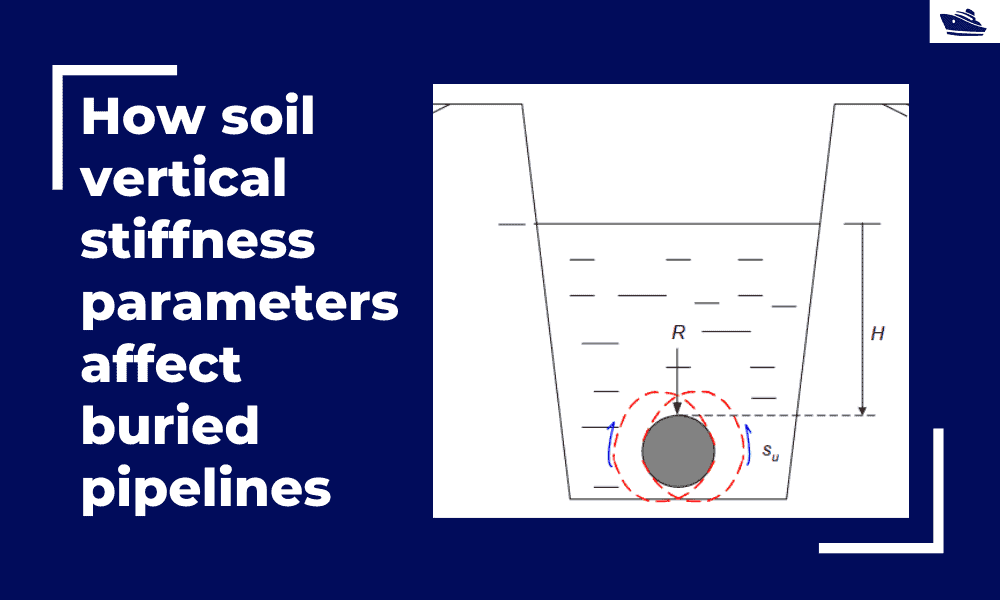
How soil vertical stiffness parameters affect buried pipelines
Introduction Pipe soil interaction is a critical subject of analysis in the field of the offshore industry. A pipe once buried in the seabed is usually in equilibrium with the surrounding soil. There are however various forces which are still in action even if the...
Three simple but useful calculations when towing a Vessel
In this article, we will explore three simple but useful calculations that can be used for towing operations. They are: Towline Stiffness Propeller race Towing bridle force DNV-RP-H1o3, Modelling and Analysis of Marine Operations, FEBRUARY 2014 has been referenced...

The why and how of freeboard calculation of a ship
Introduction Freeboard is a common term used in vessel operations. Freeboard is the smallest vertical distance between the waterline and the freeboard deck (generally the upper deck) along the length of the vessel. The term ‘smallest’ is of significance, as the height...
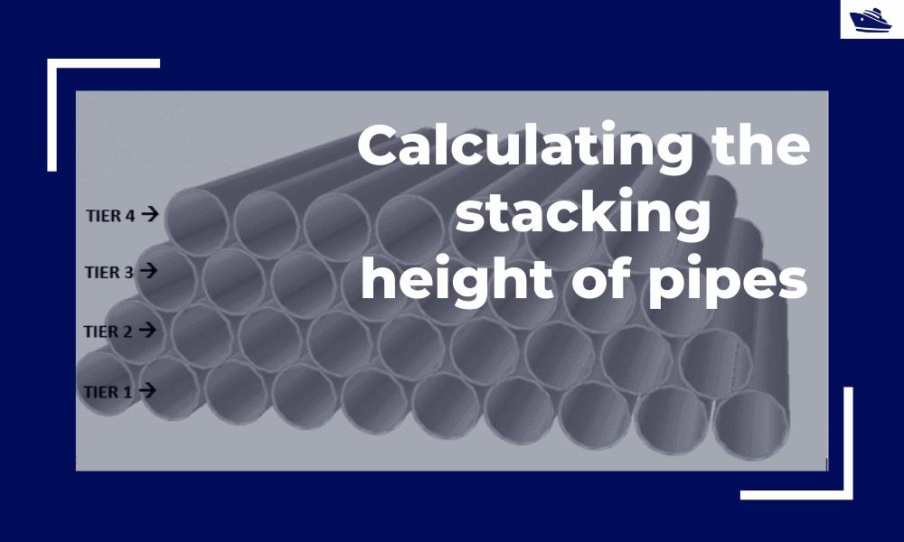
Calculating the maximum stacking height of pipes
Introduction Pipes (or linepipes or joints) are used for multiple purposes and locations in the maritime/offshore industry. Onshore and offshore pipelines are used for transportation of fluids on land, over and underwater. Pipes are fabricated in an onshore facility...
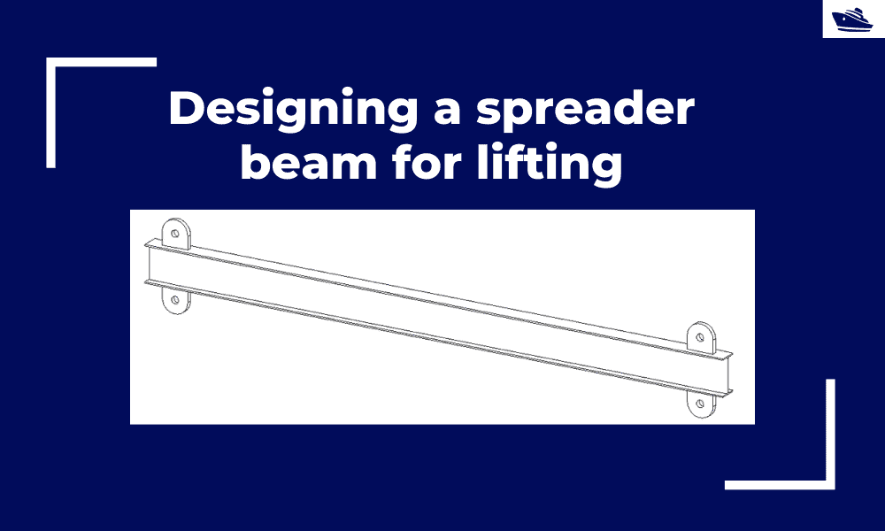
Designing a spreader beam for lifting
Spreader beams are universally applied gear which is widely used in various types of lifting operations, onshore and offshore. In this article, we will explore the design of a basic spreader beam and see what design checks are needed to establish the suitability of a...
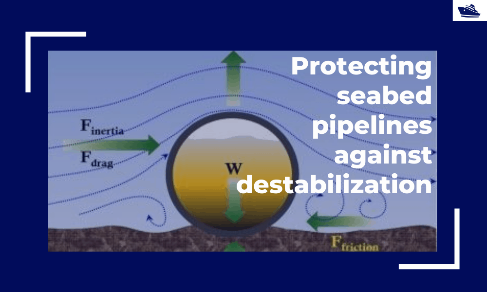
Protecting the seabed pipelines against destabilization: Identifying and qualifying the risk
The Philosophy Cable hydrodynamic stability is one of the most fundamental design topics which are addressed by cable installation engineers. In its simplest form, a simple force balance approach may be considered to ensure that the cable is not displacing...
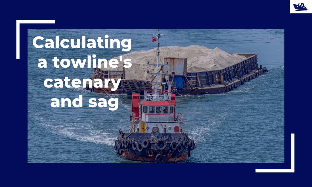
Safe Towing: Calculating a towline’s catenary and sag
Introduction Towlines connect a tug to the vessel being towed and are defined by multiple characteristics like Weight, Diameter, and Stiffness. The tension in the towline during the towing operation is not static but keeps varying with the distance between the tug and...

Thanks