*****This article first appeared in July 2018 edition of Marine Engineers’ Review (MER), India. We’re reproducing it for the readers of our blog*****
Abstract:
Since 2013, Shaft Alignment Practice has undergone a change, with developments of Analysis tools. At the Shipbuilding stage, the Classification Society approves the OEM (Original Equipment Manufacturer) document for Shaft Alignment by verifying both the procedure and the actual running condition.
Subsequently, during regular drydocking surveys, the Classification society ascertains that the initial conditions are met. In case of any damage, the Class Society jointly with the Ship Repair Team carries out various inspections to ensure its conformance. One of the tests, the Jack Loads test, is also carried out to ascertain the condition of the Alignment if required. The graph of the Jack Load test when plotted allows an experienced technician to forecast or forewarn a possible worn out bearing which can be corroborated by Shaft oil lubrication condition monitoring and bearing temperature trends.
This article aims at explaining the theory and practice of propeller shafting work, as it is being undertaken by shipyards and ship repair facilities, and we hope this will give the operators superintendents at New Buildings and Dry Dock engineers a fairly good appreciation of the subject.
Introduction:
Propeller shafting installation and alignment are subjects often discussed in connection with both the building and repairing of ocean-going vessels. Despite the availability of a plethora of information on the subject in various platforms. we often hear questions such as,
– Should we re-sight the shaft line. when ships are being dry-docked for repairs?
– How shall we re-align the shaft after the same is withdrawn for surveys?
– What is the difference between ‘gap-sag’ alignment and alignment using angular and radial misalignment?
– Is it important to do an alignment in the middle of the night for accuracy (that is when the sun is down)?
In order to understand the answers let us look at the various common propulsion systems deployed in marine crafts.
Common Shafting Systems:
Directly Coupled Shafting: This is the most common shafting installation, which we find in cargo ships. Here slow-speed engines are directly coupled to the propeller shafting and mostly employ fixed pitch propellers. The typical installation is as given in the figure-1(a)
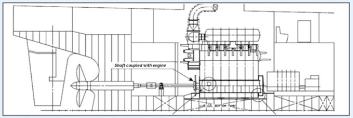
Figure 1(a) Slow speed engines with direct coupled to FPP
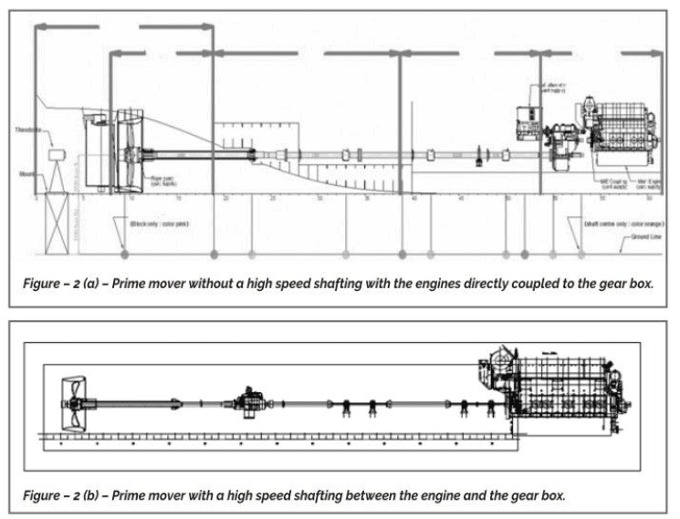
Shafting With Reduction Gear Box.
This installation is commonly found in classes of ships like workboats, naval/coastguard ships, dredgers, etc. These can be mainly two variants as shown in Figures 2(a) and 2(b). One is with a high-speed shafting between the engine and the gearbox, and the other without a high-speed shafting, the engines directly coupled to the gearbox.
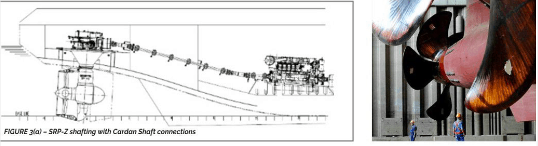
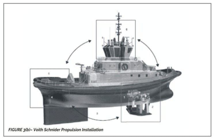
Propulsion With Thrusters
In this case, the propulsion units are installed and coupled to the prime mover directly or indirectly, with long shafting. Alignment of these propulsion units with the prime movers does not follow the conventional shaft sighting and alignment procedure.
The Theory Of Shaft Alignment:
The success in alignment is in achieving near straight shaft line during operation conditions by following a sequence and practice during the hull erection process at the new building stage. Much of the preparation is carried out during the Design stage. The shaft-line is modeled along all possible conditions from Drydock to the Afloat stage for all probable Hull deflections. The behaviors of the shaft at the various conditions are verified for limits of deviation from the straight line. Investigations are also carried out to analyze the vibrations by an iterative process of Bearing relative offsets. Subsequently, the shaft bearing reactions, jack reactions in the closed condition of the static shaft, and open condition of the shaft over the bearings are generated. Then the gap-sag readings in the open-shaft condition are generated while in afloat condition and in drydock condition while due consideration is given for the hull deflections.
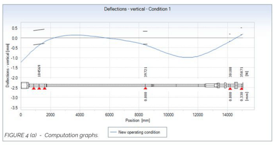
While carrying out the Iterative computations using Alignment software it is checked that the loads on bearings are commensurate with the bearing lubrication pressures designed by bearing OEM. It is also verified that no bearing is under-loaded or negatively loaded, while the alignment satisfies all Vessel representative conditions of loading. A typical computation can be seen in Figure 4 (a).
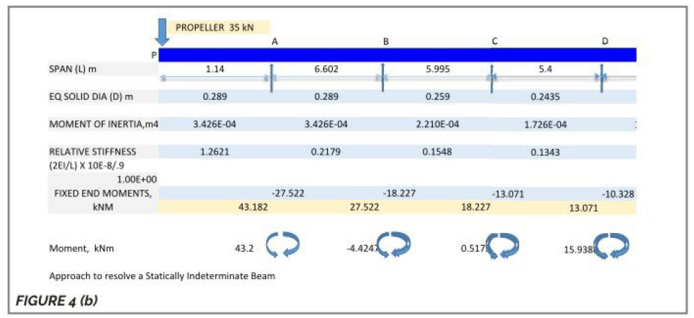
The principle of gap-sag and bearing reactions is based on the evaluation of shaft system on supports by continuous beam method. This approach Lies in resolving the statically indeterminate condition being simplified into a determinate condition by assuming an additional equilibrium process where the set slopes on either side of supports are equated.
Considerations of Hull deflections during the design stage: Using Continuous beam method with supports at Vessel. Jack points. (statically indeterminate structures), Hull deflections at the dry dock with respect to the final afloat condition can be computed. Principles can be seen in figures 4 (a) & 4 (b).
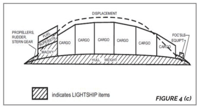
Figure 4.(c) afloat condition consideration of Vessel can be seen below.

Factors driving the New Trends and stringency:
New rules are now being drafted to introduce more stringent alignment methods. This is due to a spate of stern tube bearing wear down problems. This has come about due to various factors. The adoption of FEM methods in Hull structure design, for medium and Larger vessels to optimize on Hull scantlings, is leading to more flexible hulls. Again Finer HuLL forms are leading to Larger hull deflection from dry dock to the afloat condition and thereby more variation in the shaft line conditions. Many other factors such as the Movement of the HULL from Pre-fabrication Location to Drydock calls for re-establishing the shaft sighting and keelsighting.
Frequent stern tube bearing wear problems in pre-2013 alignments have made some OEM’s introduce stringent criteria in accepting Jack measurements.
Steps In Alignment During Building Stage:
Keel Sighting Stage:
The first step towards instaLlation of shafting and the propulsion system on any vessel is the vessel keelsighting
The first operation is keel sighting, and deciding on the keel line or baseline of the vessel, from which all measurements will be made. In a typical keel sight report of a vessel, it may be seen that the keel is not straight, but is within acceptable limits of requirement. The challenge is to decide on the optimum point from which the dimensions will be taken. The decision takes into consideration the concentricity of the shaft tine with the installed stern sections. the thickness of bolting down chocks for the main engine, gearbox and bearings on the shaft line, etc. Ideally. a chock thickness of 30 to 45 mm is preferred for a propulsion installation during the initial installation stage. This will ensure acceptable chock thickness post-launch, even after the vessel’s hull takes the final shape, and final alignment is carried out. (Note: Chock thickness more than 7o mm and less than 12mm is not preferred for propulsion installation)
Here, there is a general question asked. Should we carry out the shafting work during day time or night time? We in India prefer these jobs to be done at night, as the hull deflects considerably during the day time because of the high ambient temperature prevalent in our country. The hull more or less settles down by around nighttime. Between 220o hrs and 07oo hrs, we get a reasonably steady state of the hull, free from extreme deflections. Hence, most of the line sighting is done during these time intervals.
Methods In Sighting The Shaft Line And Shafting Installation, Pre Launch:
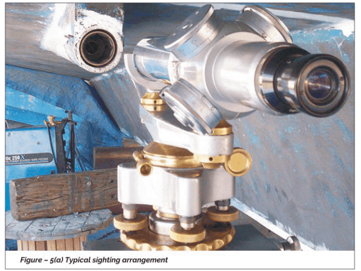
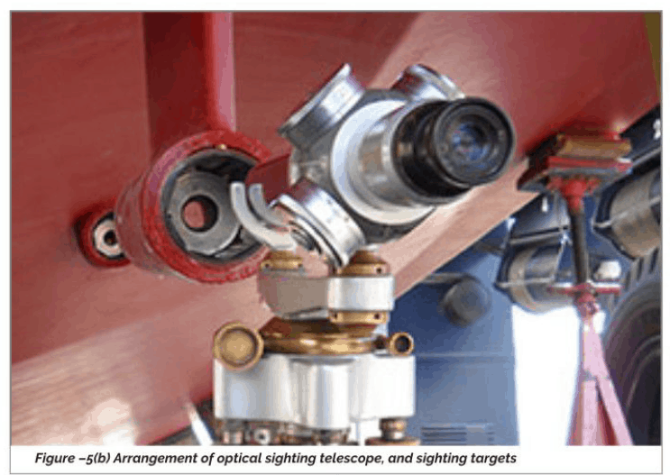
The shaft line/lines can be sighted using multiple methods/instruments. The most commonly used methods are, Sighting using piano wires, optical instruments, or using the Laser.
Whatever is the method used for the final sighting of the shaft Line, initial shaft lines are established using the following methods:
Ship center Line, shaft center lines. critical frames marked on the dock floor
The above details transferred to the ship’s hull using plumbob/Laser plumbob
Height above lines established using water levels.
Once the off-center and height above baseline of the shaft lines are established, as mentioned above. the line/lines are established, either with a piano wire or optical sighting instrument or with a Laser sighting instrument. The propeller shaft bearing housings (stern bushes) can be installed either by press-fitting to machined bores in the stern structure or can be fixed to the stern structure by resin chocking.
In the case of a machined and press-fitted bearing installation, once shaft line is sighted and signed off between the yard, owner, and the class, bearing houses are machined using line boring equipment and finished to pre determined sizes. Care is taken to ensure that the ovally and taper in the finished bore is less than the interference that is recommended between the bore and the stern bushes. Once the bore is completed, stern bushes are machined to suit, with recommended interferences and press-fitted on to the bores.
In case of a resin chocked arrangement, the stern bearing bushes are aligned to the established shaft centerline, using the yard’s sighting procedure, and fixed in position with resin chocks. Once the bearings are fixed. Stern tube Lub oil piping and aft seal oil supply piping is completed, for oil-cooled installation.
For both oil-cooled and water-cooled installations, bearing temperature sensors are also installed at this stage.
Now the installation is ready for shafting insertion. Shafts are inserted from inboard or outboard, depending on the type of installation. For most of the conventional fixed pitch propellers. the shaft is inserted from inside the vessel. and for CPP propulsion the shaft is inserted from outside.
Once the shafts are in position, propeller is installed for a fixed-pitch propeller. The propeller is attached to the matching portion on the shaft and pushed up, as per the requirement of the propeller OEM.
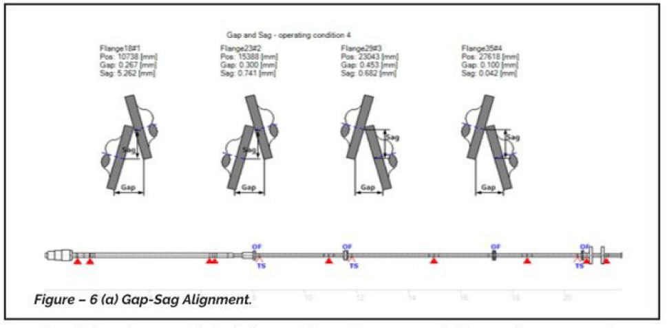
After the fitment of the propeller/CPP propeller shaft, seals in the forward and aft are tightened for oil cooled installations. After this rope guards are fixed. The shaft installation is locked for protecting the same from slipping during launching/float out. The propeller shaft is pushed back by about 5-6mm (within the movement allowed by the seals) prior to locking of the shaft. This is to ensure enough gap between the shafts/engines/gearboxes for carrying out gap and sag alignment.
On completion of gap and sag alignment, and once the engine/gearbox is in position, this distance is pulled in to complete the installation,
Post Launch Alignment Activities: Final alignment of the shaft Line, the coupling of the various elements of shafting, final fixing of engines/gearboxes, pedestal bearings are carried out post launching of the vessel. This again depends on the experience of the shipyard and the data of previous vessels available to the yard. For example, many of the Japanese and Korean shipyards carry out most of the jobs that are done in the post-launch stage at the pre-launch stage itself, and post-launch only a verification of the job done is carried out for confirmation.
However, in Indian shipyards, most of the final alignment work is carried out post Launching of the vessel.
Condition Of Vessel For Post Launch Alignment:
In the case of larger cargo vessels, the alignment is usually carried out in the Launching draft of the vessel. However, for vessels with smaller size and Lesser draft, the ship is brought to even keel, with propeller immersion prior to carrying out final alignment. It is always desirable to keep the condition of the vessel unaltered during the course of alignment of the vessel, even though it may not be always practical.
That brings up to the end of Part 1 of this topic. In part 2, we’ll see the following
- Carrying out gap-sag alignment
- Evaluation of bearing reaction/load
Disclaimer: This post is not meant to be authoritative writing on the topic presented. thenavalarch bears no responsibility for the accuracy of this article, or for any incidents/losses arising due to the use of the information in this article in any operation. It is recommended to seek professional advice before executing any activity which draws on information mentioned in this post. All the figures, drawings, and pictures are property of thenavalarch except where indicated, and may not be copied or distributed without permission.
Webcast: Rapid Rigging
Learn a rapid and practical method for generating accurate rigging arrangements and estimating rigging loads in one hour or less using simple engineering principles and streamlined workflows. TECHNICAL WEBCAST OVERVIEWLifting operations can be executed far more...

TheNavalArch’s Interview Series: Peter Farthing (MD, Sensor Technologies)
Peter FarthingManaging Director of Sensor Technologies Ltd and CEO of Advantec Group Limited Interview Introduction TheNavalArch's Interview Series is an endeavor to get insights from the best engineering and business brains in the industry and present them to its...
TheNavalArch Interview Series: Capt Robin Perera
TheNavalArch's Interview Series is an endeavor to get insights from the best engineering and business brains in the industry and present them to its users for the larger benefit of the maritime community. Leaders share their experiences and ideas that readers can gain...
Offshore Installation Vessels Stability Considerations
OFFSHORE INSTALLATION VESSELS STABILITY CONSIDERATIONS By Alan Crowle, BSc, MSc, MScbyRes, CEng, CMarEng, FRINA, FMAREST, FSCMS University of Exeter, College of Engineering, Renewable Energy Group INTRODUCTION The temporary phases of an offshore structure transport...
TheNavalArch Interview Series: Mr Victor Valera
TheNavalArch's Interview Series is an endeavor to get insights from the best engineering and business brains in the industry and present them to its users for the larger benefit of the maritime community. Leaders share their experiences and ideas that readers can gain...
TheNavalArch Interview Series: Mr Steven Lu
Mr. Steven LuManaging DirectorEpoch Offshore Engineering (Shanghai) Co., Ltd. TheNavalArch's Interview Series is an endeavor to get insights from the best engineering and business brains in the industry, and present them to its users for the larger benefit of the...
TRANSPORT VESSELS FOR FLOATING WIND
By Alan Crowle, BSc, MSc, CEng, CMarEng, FRINA, FMAREST, FSCMS Masters by Researcher, University of Exeter, College of Engineering, Mathematics and Physical Sciences, Renewable Energy Group SUMMARY Floating wind turbine construction is a large logistical exercise. The...
TheNavalArch Interview Series: Mr. Balakrishna Menon
Mr. Balakrishna MenonEngineering Director Mooreast (Asia) Pte Ltd TheNavalArch's Interview Series is an endeavor to get insights from the best engineering and business brains in the industry, and present them to its users for the larger...

Floating Rice Fields, the quest for solutions to combat drought floods and rising sea levels
by Lim Soon Heng, BE, PE, FSSS, FIMarEST Founder President, Society of FLOATING SOLUTIONS (Singapore) Abstract Amazing as it seems, there is a case for growing rice on floating platforms in the sea. The capital expenditure to develop this is offset by the opportunity...
CAPSIZE OF LIFTBOAT IN TRANSIT
This paper was originally presented in the 27th Offshore Symposium, February 22nd, 2022, Houston, Texas Texas Section of the Society of Naval Architects and Marine Engineers It has been reproduced here for the readers of TheNavalarch INTRODUCTION In 1989 a Class 105...

shaft targeting wiith electronic appliances
aapody223@gmail.com
The online articles published by The Naval Arch Team are current, relevant and invaluable to the maritime operators of the present day. Thank You. Well Done!