Introduction
The windage area of a vessel or offshore structure is the area that is exposed directly to the wind. As is obvious, this is the area of all items above the waterline. This will include
- Part of the hull/offshore structure above the waterline
- Superstructure/Living Quarters
- Any deck cargo
Calculating the windage area is required when we need to know the wind forces acting on the vessel. The formula for wind force calculation on any structure is:
Wind Force = Pressure x Area exposed to the wind direction
Pressure is given as Pressure = ½ ρV2, where ρ is the density of wind, which is generally taken as 1.23 kg/m3, and V is the wind speed in m/s. The area exposed to the wind direction is also called ‘Windage area’
This article explores the intricacies involved in both the calculation of wind speed and the calculation of the windage area. We take a look at four important factors – Wind Speed & Direction, Height Factor, Shape Factor, and Shielding effects.
Windage Area
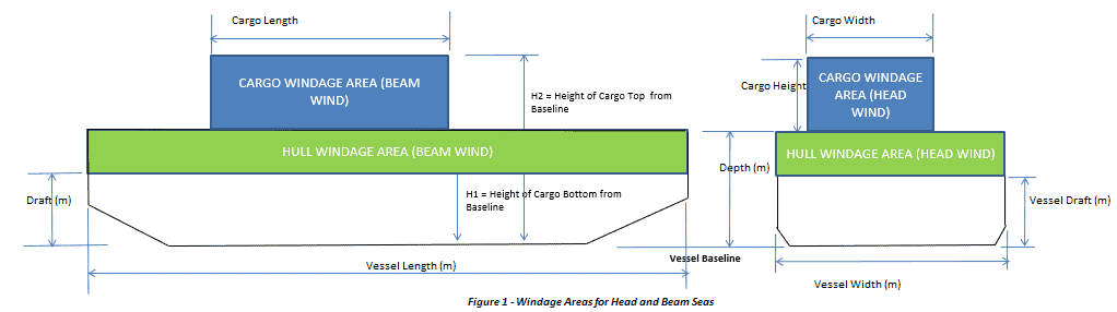
The windage area of a structure is the area exposed to the wind projected at a section that is perpendicular to the wind direction. The windage area from different directions will also be different, depending on the geometry of the structure. This is illustrated in the figure below. We can see that when the wind is from the transverse direction (beam wind), the exposed area of the cargo to the wind is Length x Depth, while for the wind from longitudinal direction (head wind), the exposed area is Breadth x Depth, which is lesser.
What if the wind is not in the transverse or longitudinal direction? What if it is at an angle to the longitudinal axis of the structure? How do we calculate the windage area?
For such cases, there’s a simpler way of estimating the wind force if the transverse and longitudinal windage areas are known. Referring to PNA Vol 2, Sec 5.2, Eq 26 [Ref 2], we can see from the figure below
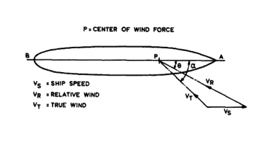
Wind angle calculations (Ref [2])
FW = K * ρair*VR2*(AL sin2θ + AT cos2θ)/cos (α – θ) ………………… (Formula A)
Here the vessel is moving forward with a speed VS, while the true wind is VT at an angle α to the longitudinal axis of the vessel. AL and AT are the projected windage areas for head and beam wind. The value of K varies between 0.5 and 0.65 and is generally taken as 0.6. The above equation can be used even for head and beam wind directions.
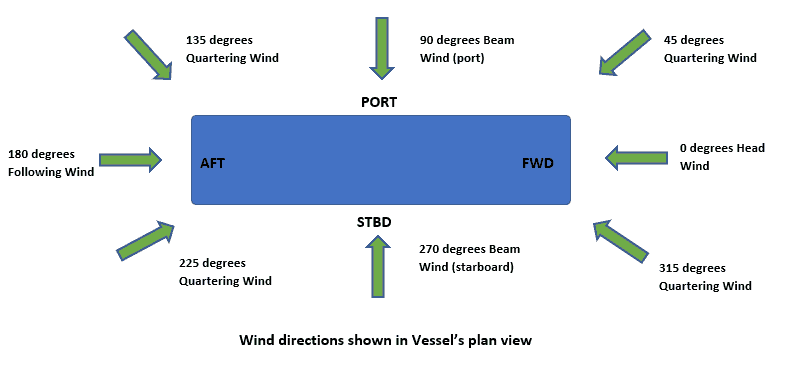
Wind Speed and direction
Wind speed is simply the speed at which the wind is blowing. However, it is the direction and height at which the wind is blowing that assume significance when calculating the wind load on a structure. The wind speed can be different in different directions, resulting in varying wind loads. The dominant wind direction and speed have to be taken into consideration for design purposes.
Height Factor
At the same time, the speed of wind also varies with the height of the structure above the water surface. Generally, the wind speed is higher at higher levels of a structure. The effect of height is taken into account by adding a factor called ‘height factor’ in the calculation of the windage area. A structure is divided into different ‘height zones’ depending on its height from the sea level, and different height factors are applied to the windage area of different zones. The height factor can be obtained from standard references like ABS Rules [Ref 1]. These are shown in the figure below:
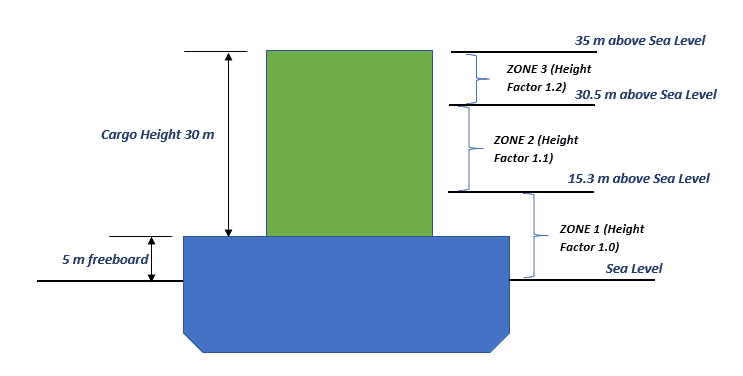
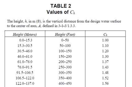
Height factor for different zones (Ref [1])
Shape factor
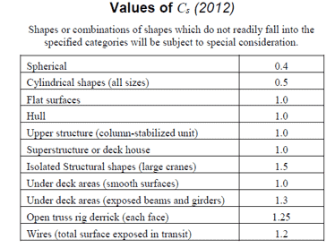
The shape of a structure exposed to wind also influences the wind force that it experiences. For example, a cylinder when exposed to wind will experience lesser force compared to a flat plate of the same projected area exposed to the same wind. The effect of shape on wind force is accounted for by adding a shape factor to the calculation of the windage area. Shape factor can be obtained from standard references like ABS Rules [Ref 1]
Shielding effects

When one structure is blocked by another structure in front of it (the windward frame), then the wind force on the first structure (leeward frame) is expected to be less, and it is called ‘shielded’ by the second structure. This ‘shielding effect’ can be taken into account by factoring the windage area of the shielded structure by a factor called ‘shielding factor’. The shielding factor for a particular structure depends on how solid is the windward frame, and what is the shape of the members comprising the windward frame. DNV-RP-C205 Sec 5.3.3 [Ref 3] provides detailed tables for calculating shielding effects. For a conservative calculation, shielding effects can be ignored.
Calculation
With the understanding of the above factors in wind load calculation, the whole process can be developed into a spreadsheet application that takes as input the details of the vessel, its superstructure and cargo, and calculates the factored windage areas for each of them.
The calculation steps are lined out below:
- Take the vessel’s geometry details from the user. The vessel’s wind area is the part of the vessel above water, i.e., the freeboard of the vessel. The freeboard is divided into different ‘height’ zones depending on how high the freeboard is. From ABS Rules for Building and Classing Mobile Offshore Drilling Units, 2019, C 3-1-2/1.3.2, we can see that the height coefficient is 1.0 for a freeboard of up to 15.3 m. If the vessel’s freeboard is more than 15.3 m (which is generally rare), then the zone of the hull that is at a height more than 15.3 m from the waterline will have to be assigned a height coefficient of 1.1.
- If A1 is the area in Zone 1 (below 15.3 m from waterline), and A2 is the area in Zone 2(more than 15.3 m from the waterline, but less than 30.5 m from waterline), then the total windage area factored for height will be A = 1.0 x A1 + 1.1 x A2. This applies to both longitudinal or transverse areas
- The shape coefficient for the hull is generally taken as 1.0, as the part of the hull above the freeboard is generally flat with near rectangular section.
- Apply a similar method as for the hull to Superstructure and cargo
- For each item, calculate the effective windage area by factoring the different zones with different height coefficients
- Shape coefficients will have to be assigned depending on the shape of the item facing the wind
- The shape coefficient may be different in transverse and longitudinal directions, depending on the shape difference of the cargo in the two directions
- Shielding effects can be applied by following DNV-RP-C205
- If the wind force is required in a direction other than transverse or longitudinal, then use Formula A to get the results
Following the steps above, a fair assessment of the wind forces on a structure can be done.
That brings us to the end of this article. We hope this was useful to you. Please do check TheNavalArch’s own product for windage area calculations that helps you perform this calculation effectively and with a simple user interface.
References
- ABS Rules for Building and Classing Mobile Offshore Drilling Units, 2019, C 3-1-2/1.3.2
- Principles of Naval Architecture, Vol 2, Sec 5.2, Eq 26
- DNV-RP-C205, Sec 5.3.3
Disclaimer: This post is not meant to be authoritative writing on the topic presented. thenavalarch bears no responsibility for the accuracy of this article, or for any incidents/losses arising due to the use of the information in this article in any operation. It is recommended to seek professional advice before executing any activity which draws on information mentioned in this post. All the figures, drawings, and pictures are property of thenavalarch except where indicated, and may not be copied or distributed without permission.
Webcast: Rapid Rigging
Learn a rapid and practical method for generating accurate rigging arrangements and estimating rigging loads in one hour or less using simple engineering principles and streamlined workflows. TECHNICAL WEBCAST OVERVIEWLifting operations can be executed far more...

TheNavalArch’s Interview Series: Peter Farthing (MD, Sensor Technologies)
Peter FarthingManaging Director of Sensor Technologies Ltd and CEO of Advantec Group Limited Interview Introduction TheNavalArch's Interview Series is an endeavor to get insights from the best engineering and business brains in the industry and present them to its...
TheNavalArch Interview Series: Capt Robin Perera
TheNavalArch's Interview Series is an endeavor to get insights from the best engineering and business brains in the industry and present them to its users for the larger benefit of the maritime community. Leaders share their experiences and ideas that readers can gain...
Offshore Installation Vessels Stability Considerations
OFFSHORE INSTALLATION VESSELS STABILITY CONSIDERATIONS By Alan Crowle, BSc, MSc, MScbyRes, CEng, CMarEng, FRINA, FMAREST, FSCMS University of Exeter, College of Engineering, Renewable Energy Group INTRODUCTION The temporary phases of an offshore structure transport...
TheNavalArch Interview Series: Mr Victor Valera
TheNavalArch's Interview Series is an endeavor to get insights from the best engineering and business brains in the industry and present them to its users for the larger benefit of the maritime community. Leaders share their experiences and ideas that readers can gain...
TheNavalArch Interview Series: Mr Steven Lu
Mr. Steven LuManaging DirectorEpoch Offshore Engineering (Shanghai) Co., Ltd. TheNavalArch's Interview Series is an endeavor to get insights from the best engineering and business brains in the industry, and present them to its users for the larger benefit of the...
TRANSPORT VESSELS FOR FLOATING WIND
By Alan Crowle, BSc, MSc, CEng, CMarEng, FRINA, FMAREST, FSCMS Masters by Researcher, University of Exeter, College of Engineering, Mathematics and Physical Sciences, Renewable Energy Group SUMMARY Floating wind turbine construction is a large logistical exercise. The...
TheNavalArch Interview Series: Mr. Balakrishna Menon
Mr. Balakrishna MenonEngineering Director Mooreast (Asia) Pte Ltd TheNavalArch's Interview Series is an endeavor to get insights from the best engineering and business brains in the industry, and present them to its users for the larger...
Floating Rice Fields, the quest for solutions to combat drought floods and rising sea levels
by Lim Soon Heng, BE, PE, FSSS, FIMarEST Founder President, Society of FLOATING SOLUTIONS (Singapore) Abstract Amazing as it seems, there is a case for growing rice on floating platforms in the sea. The capital expenditure to develop this is offset by the opportunity...
CAPSIZE OF LIFTBOAT IN TRANSIT
This paper was originally presented in the 27th Offshore Symposium, February 22nd, 2022, Houston, Texas Texas Section of the Society of Naval Architects and Marine Engineers It has been reproduced here for the readers of TheNavalarch INTRODUCTION In 1989 a Class 105...

how can calculate the windage area for a Tangeri with 14,7 mtrs of max draft ,lenght 240 mtrs large 42 mtrs
Hi Pietro, can you send us the GA of the vessel to info@thenavalarch.com? Thanks
Very well presented