Over the last 20 years, the interest in offshore wind power generation has increased substantially. Offshore Wind Energy currently provides only 0.3% of world power generation, but the potential is really vast. In the next 20 years the offshore wind industry is set to become a trillion dollar business[1]. Not only the offshore wind-parks are growing in size as well as numbers across the globe, the wind generating turbines are also growing in size by 16% per year[2]. Offshore power systems include power generation units, power transmission and power distribution.
Power transmission can be performed from power generating turbines directly to the land, or to an offshore substation, from which the power is transmitted over large cables. A 700MW offshore wind-park would require tie-in of approx. 70 towers with a total of 70-80kms of inshore / array cables and 40-50kms of export cable laid away from coast. This volume of heavy cables is stored and installed using a specialized cable lay vessel (CLVs).
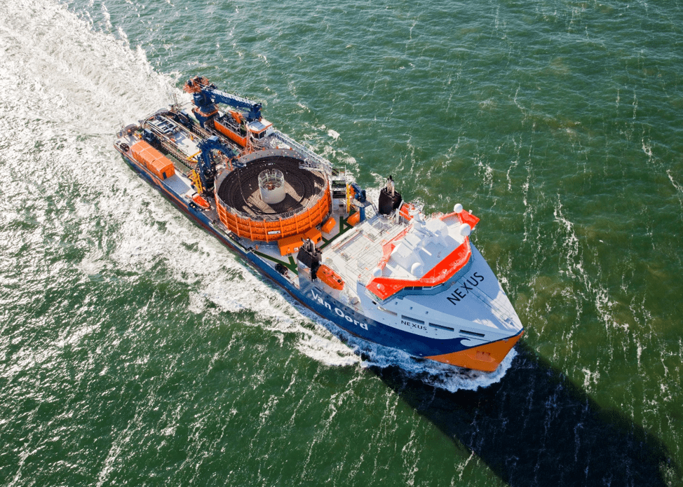
Figure 1: Typical Cable Lay Vessel (Courtesy: Van Oord)
An installation project could last from multiple months to up-to 1.5 years. Increased offshore activity, lasting offshore presence and widespread footprint exposes the cables and CLVs to severe storms as well as fishing activities. Although cables and transmission costs amount to around 20% of total project cost, they may form up-to 80% of total insurance claims[3]. This suggests there is ample knowledge gap in the cable installation industry to be bridged. Cable installation comes with its own set of risks. What are they?
- The locations where the offshore assets are installed are ‘expected’ to have strong winds, which usually are correlated with higher sea-states. Operating cable lay vessels with a live catenary in such treacherous weather is all the more difficult. Past has shown frequent anchor line damages, Dynamic Positioning (DP) run-offs and vessel instability. Crane operation further imposes a limiting condition on vessel operability.
- Seabed depths , Seismic activities, seabed slopes, soil bearing capacities, presence of boulders in the region can make subsea cable unstable with introduced free-spans. This also puts a big challenge on economic feasibility as well as operation suitability of burial and trenching tools. If a cable lands on UXOs (unexploded ordinances, includes unexploded bombs, landmines, toxic fluid releases) , it can not only damage the cables but also have lasting impact on the marine life.
- Cable properties: Unlike pipelines, cables are relatively light and quite susceptible to current and wave loads. The cables have been difficult to stabilize in hard soils. But relatively heavy transmission cables necessitate larger storage and operational equipment. Further, cable manufacturers impose higher cable handling restrictions which make it difficult to operate with the existing tools on the vessels.
- Type of asset: Pulling cable through J-tubes and monopiles has not been easy. Different pull-in structures are shown in Figure 2. While expensive and bent J-tubes can offer considerable friction and high pull-in loads, monopiles require unique and tailormade cable protection systems. Sometimes cables are also pulled through concrete structures.
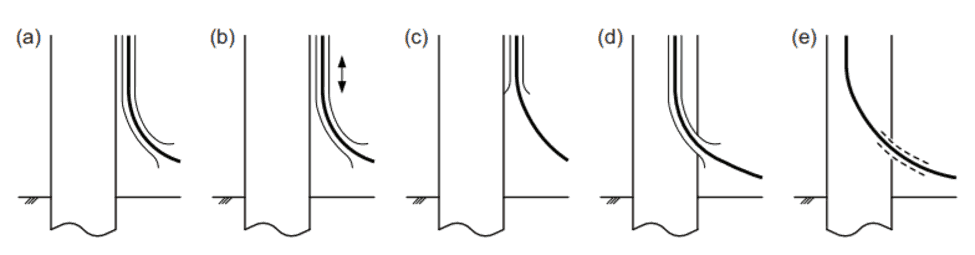
Figure 2: (a) External J tube (b) Movable J tube (c) I tube (d) Internal J tube (e) Monopile J tube less
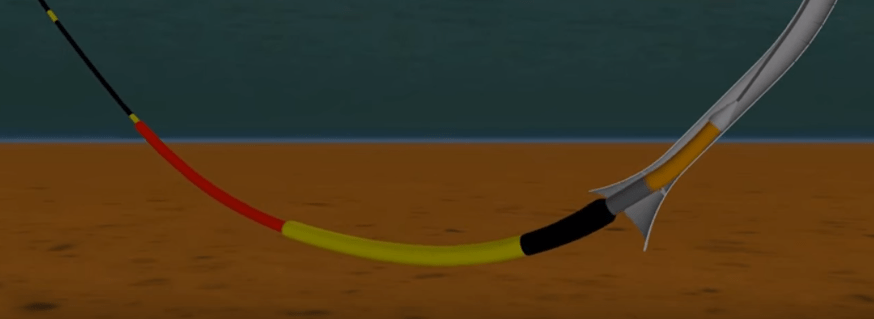
Figure 3: Cable pulled-in through J tube
- Accidental dropping of anchors and fishing activity in the area.
- Local legislation requirements: Required higher burial depth due to nautical traffic
- Logistics: transporting cables using barges in rivers and shallow water requires appropriate under-keel clearance. Delay in delivery of cables leads to progressive delays.
- Site permits, contract issues: A very expensive affair!
- Decommissioning of offshore field: Pull-out and retrieval of the cable. Further, recovery, joining and re-lay of the cable have their own costs.
Knowledge and pre-assessment of the technological risks are the first step towards risk mitigation. Before finding solutions to prevent cable failures, one must assess what design or operational limit is sufficient for preventing a risk.
Note that cable installation is a new industry which derives much of its knowledge from the matured pipelaying industry. Many of the recommended practices and offshore standards are directly derived from classification society rules meant for pipelines. While the design philosophy is similar in various fronts, the quantification of cable-soil interaction, cable material and mechanical properties etc. require cable specific documentation and formulations. The most popular code for calculations relevant for installation and as-installed condition of cables are the DNVGL Guidelines. The formulations and calculation methods in these guidelines are based on wide experiences from the industry’s leading contractors and manufacturers contributing to the Joint Industry Projects (JIPs).
For instance, the Installation contractors, which perform cable installation from cable installation vessels only within a short weather window must refer to Marine Operation and Marine Warranty Guidelines “DNVGL-ST-N001”, an extensive guideline for the set of rules and guidelines which both the installation engineers and marine warranty surveyors shall refer to.
However, a designer of a permanently installed asset like cable must refer to specific DNVGL guidelines which are relevant for the subject. For example:
• DNVGL-RP-C205: Environmental parameters
• DNVGL-RP-F105: Free-spanning pipelines
• DNVGL-RP-F107: Dropped Objects
• DNVGL-RP-F109: On- bottom stability of the submarine pipelines
• DNVGL-RP-F110: Global buckling of subsea pipelines
• DNVGL-RP-F114: Pipe soil interaction etc.
Also, there are various subjects which are not covered within the DNVGL guidelines but there is substantial literature in the public domain for reference. We, at TheNavalArch, strive to understand the theoretical explanations from the literature and aim to automate the methods into easily extractable and readable outputs. We use mathematical simplifications of multiple formulations in the guidelines so as to empower the engineer to get a straightforward outputs or tables and graphs which are clear to extract conclusions. The easy-to-use tools we have created are useful for Tender Engineers, Project Engineers, Offshore Construction Managers and even Consultants of Engineering firms to perform quick calculations on site while validating calculations of the third party solution providers. For the more complicated procedures, we aim to process a large database of calculations and generate statistics based parametrical relationship.
The tools we have created so far for cable calculations are as follows :
- Free-spanning pipeline calculator
- Subsea Cable Calculators
- J tube force assessment
- Wave scatter generator
- Dropped Object Calculator (upcoming)
- On-bottom stability tool (upcoming)
Watch this space for more product launches in future.
[1] WindEurope Annual Report- Offshore Wind in Europe Key trends and statistics 2019
[2] International Energy Agency Press Release December 2019
[3] https://www.4coffshore.com/news/submarine-power-cable-losses-totalling-over-eur-350-million-in-claims-nid5127.html
Disclaimer: This post is not meant to be an authoritative writing on the topic presented. thenavalarch bears no responsibility for any incidents or losses arising due to the use of the information in this article in any operation. It is recommended to seek professional advice before executing any operation which draws on information mentioned in this post. All the figures, drawings and pictures are property of thenavalarch except where indicated, and may not be copied or distributed without permission.
Getting the right thickness of GRP laminate for your boats
Introduction GRP laminates are widely used in the fabrication of high-speed crafts and light crafts/boats globally. GRP stands for Glass Reinforced Plastic. As the name suggests, GRP contains glass fibers embedded into a plastic resin. This gives it higher strength,...
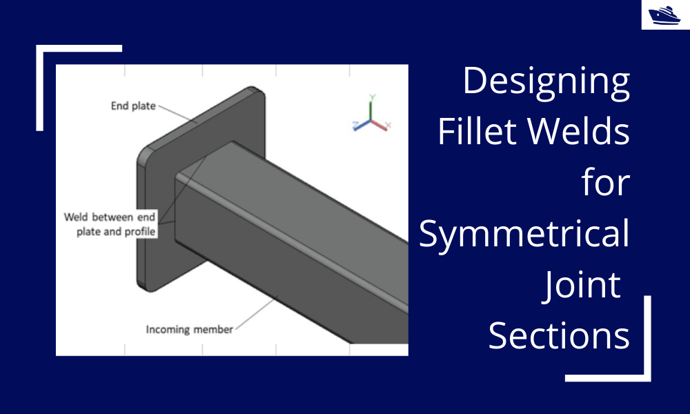
Designing Fillet Welds for Symmetrical Joint Sections
Introduction Fillet welds are the most commonly used weld types in marine structures. A fillet weld is used when there are two pieces of metal that are joined perpendicular to each other or at an angle. In this article, we will explore how to select the right size...
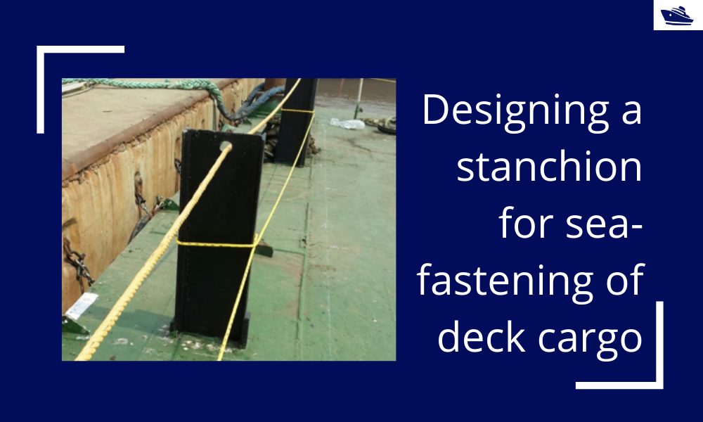
Designing a stanchion/stopper for sea-fastening of deck cargo
Introduction Stanchions – a familiar term for mariners and ship designers. What are Stanchions? A stanchion is generally a vertical pipe or beam which is used to support some structural item or provide support rails on the deck. In ships, the most common type of...
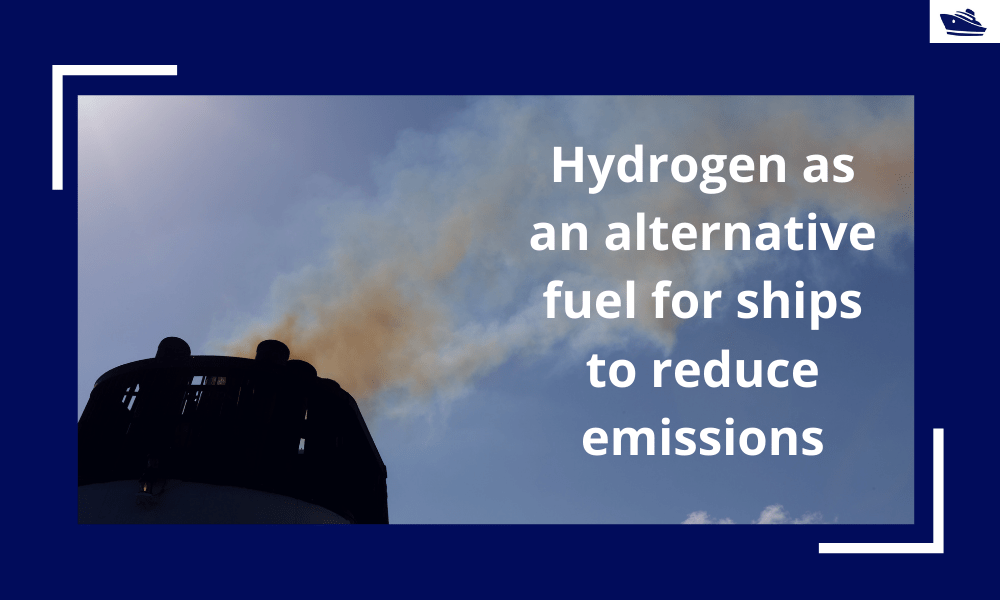
Hydrogen as an alternative fuel for ships to reduce emissions
,This article first appeared in the Feb 2019 edition of Marine Engineers Review. It is being reproduced with minor edits here for the readers of TheNavalArch's blog. Introduction The world is on facing a grave environmental challenge with an increase in carbon...
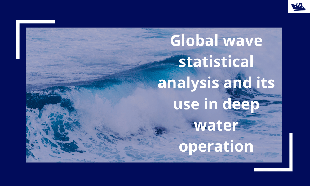
Global wave statistical analysis and its use in deepwater operations
Why do we need wave analysis? For the design of offshore operations such as installation and transport of offshore structures, as well as lifecycle design of floating and fixed structures, knowledge of extreme waves as well as the probability of different sea-states...
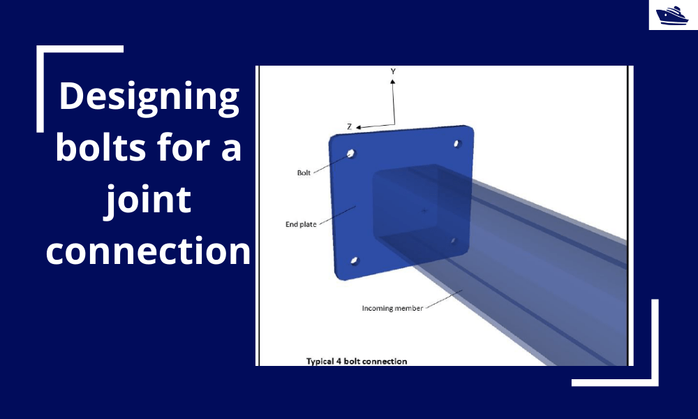
Designing bolts for a joint connection
Introduction Bolts are very commonly used fastening items and used in a variety of configurations. In this article, we will explore in-depth the design of a bolt used in connecting two members at a joint (bolted joint). We'll see what properties of the bolt are...
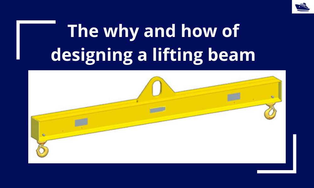
The why and how of designing a lifting beam
Lifting beams are universally applied gear used widely in various types of lifting operations, onshore and offshore. In this article, we will explore the design of a basic lifting beam and see what design checks are needed to establish the suitability of the beam for...
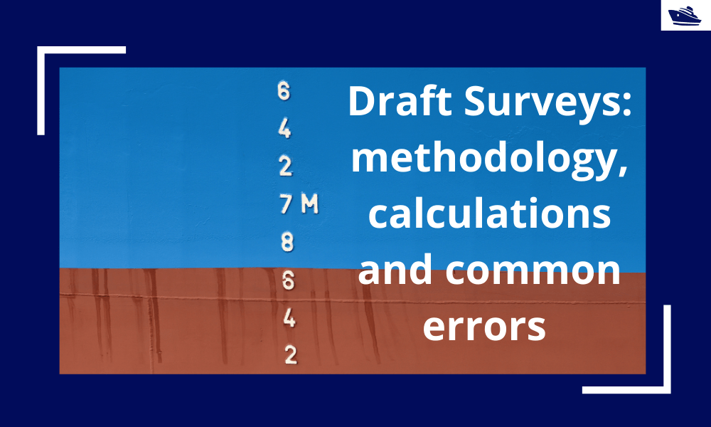
Draft Surveys: Methodology, Calculations, and common errors
Introduction Marine transport is the backbone of the global trade and reasonably can be considered to be the artery of the global manufacturing supply chain, as more than four fifths of the world merchandise trade by volume is carried by sea. Undoubtfully, the...
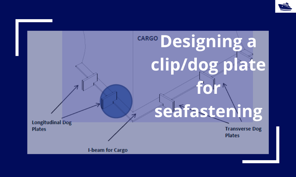
Designing a clip/dog plate for seafastening
Introduction In an earlier article, we saw how to design stoppers for seafastening. Stoppers are items that are used to contain the translation movements (longitudinal and transverse directions) of a cargo on the deck/hold of a vessel. That brings us to the question –...
The Bulbous Bow – types, characteristics, and effects
This is Part 2 of the two-part series on Bulbous Bows. For Part 1, click here By Tamal Mukherjee, *This article originally appeared in May 2019 edition of Marine Engineers Review (India), the Journal of Institute of Marine Engineers India. It is being...

interested in learning risk associated with cable laying and insurance coverages.
i have interest to know more detail in under sea cable installation