Introduction
Over the last 10 years, the global wind energy business has increased manifold. In the next 5 years, the rate of installation is expected to accelerate. This is mostly driven by the opening up of Chinese and US markets. A primary chunk of this market is driven by offshore wind energy development. Such is the importance of the business that even during the COVID-19 pandemic, the wind capacity increased by 8% (https://www.iea.org/reports/renewables-2020/wind, 2020)
An offshore wind farm is connected to the land-based grid via a large transmission cable called Export cable. The cable is laid either from the turbines directly, or via a Transformation station located offshore towards the shore. The length of the export cable can be a few kilometers to up to 50 kilometers.
Usually, the entire cable length is stored on an installation vessel (Cable Laying Vessel CLV) which lays the cable between the shore to the substation. The ends of the cable shall be pulled in at both ends using external winches and tensioners.
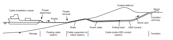
The nearshore pull-in operation is performed by pulling the cable all the way from the vessel moored /beached offshore towards the shore using a pull-in winch. The length of the cable paid out from the vessel is not dragged on the seabed, but is floated using buoyancy units. Once the cable reaches the shore, the buoyancy units are removed by personnel onshore and the cable is pulled over the rollers. There are locations where the cable could be pulled around a bent section, which adds additional frictional resistance. Lastly, the cable could be pulled underneath fixed assets (buildings, roads, railroads, dykes) through a duct (HDD). The cable is paid out using a vessel tensioner and pulled in using a winch. Sometimes, due to excessive load, additional track tensioner/winches may be installed along the path.
Challenges
Some challenges relevant for nearshore pull-in operation is as follows:
- The shallow depth on site: The operation is performed in a very shallow depth. As a result, the CLV usually cannot approach the shore due to its large draft. If the vessel does not have beaching ability (i.e. the bottom of the vessel is flat and the vessel thrusters are retracted), the vessel needs to be positioned much further away from the shore. This leads to an operational footprint spanning up to few kilometers from the shoreline (both inland and offshore).
- Friction: Due to the landside operation, a number of roller boxes are placed on the shore over which the cable is pulled over. Due to the long route length, there could be more than a few hundred roller boxes placed along the length. Due to the wet sand, tidal variations, age of roller boxes and misalignment, the rollers can be inefficient. As a result, the friction can increase considerably, leading to very high-end loads. The friction load is calculated as per Sheave formulation over a bend with angle Θ :
T=T0 eμθ
Thus the resulting friction after a bend is directly impacted by the tension before any bend.
- Current and weather window: Although the waves aren’t very significant on the shore, the current can have a significant impact on the cable drift, due to excessive drag due to the buoyancy units. A small increase in current can have a significant impact on the cable loads as not only more cable length is dragged out of the vessel, but it also linearly increases the end tension, due to the sheave friction formula, shown above. Note also that due to the shallow depth, the vessel may ground with small waves too. That’s why the operation has a restricted weather window and time is of great essence.
It is because of such challenges that the pull-in operation is closely engineered with the fullest awareness of details. Typically, the shore profile and soil characteristics are closely surveyed and roller boxes are carefully placed. The route is cleared of boulders and other obstructions. Because of any misalignment of height, there can be locations with high point loads on the vessel. These things make nearshore pull-in a critical operation. Because of its own challenges, the nearshore operation is sometimes treated as a standalone project.
Checklist
Prior to the commencement of operation, the engineers must make gross preparation to estimate the loads on the cable and the tensioners. Through a comprehensive analysis, the engineer must decide on :
- Where to position the vessel (with respect to high-low tide)?
- In which weather window can the pull-in be commenced?
- What kind of floatation do they need to use?
- How to optimize the path of the pull-in of cable?
- Where to place quadrants, winches, powered tensioners, assisting bulldozers etc.?
- HDD shape optimization?
- The capability of cable to sustain the loads?
We, at TheNavalArch, have recognized the need for a standard calculation approach for this critical operation. We have researched a simplified and median approach that can be applied across the global contractors. This not only saves precious engineering time but also eliminates errors by treating the calculation template as a check-list for any third-party verification.
Watch out this space for the upcoming launch of the tool
Disclaimer: This post is not meant to be an authoritative writing on the topic presented. thenavalarch bears no responsibility for any incidents or losses arising due to the use of the information in this article in any operation. It is recommended to seek professional advice before executing any operation which draws on information mentioned in this post. All the figures, drawings and pictures are property of thenavalarch except where indicated, and may not be copied or distributed without permission.
Marine Propeller Shafting and Shafting Alignment – Part 1
*****This article first appeared in July 2018 edition of Marine Engineers' Review (MER), India. We're reproducing it for the readers of our blog***** Abstract: Since 2013, Shaft Alignment Practice has undergone a change, with developments of Analysis tools. At the...
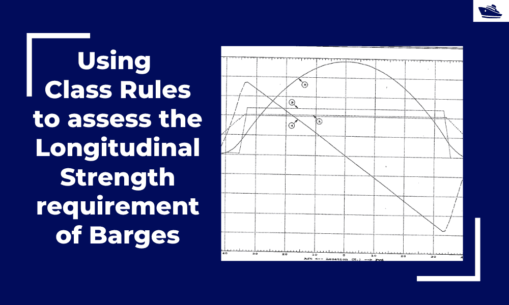
Using Class Rules to assess the Longitudinal Strength requirement of Barges
Introduction The longitudinal strength of a vessel is integral to its evaluation for a given purpose. To get an introduction to the topic, please refer to our other article https://thenavalarch.com/longitudinal-strength-ships-introduction/ In this article, we’ll see...
The four important factors for a ship’s windage area calculations
Introduction The windage area of a vessel or offshore structure is the area that is exposed directly to the wind. As is obvious, this is the area of all items above the waterline. This will include Part of the hull/offshore structure above the waterline...
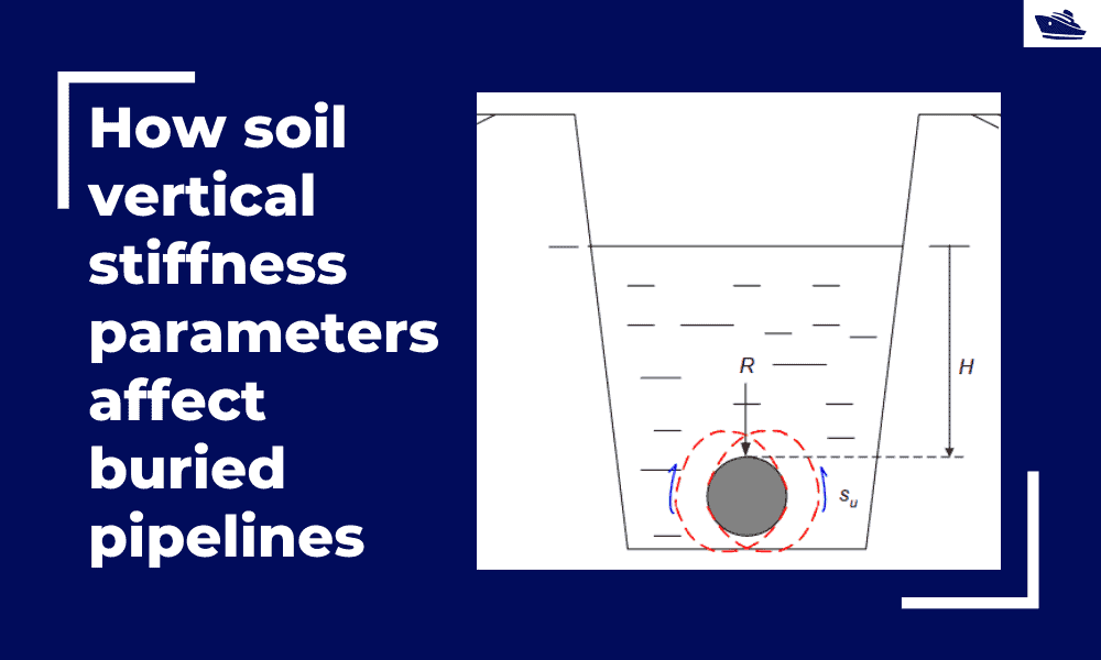
How soil vertical stiffness parameters affect buried pipelines
Introduction Pipe soil interaction is a critical subject of analysis in the field of the offshore industry. A pipe once buried in the seabed is usually in equilibrium with the surrounding soil. There are however various forces which are still in action even if the...
Three simple but useful calculations when towing a Vessel
In this article, we will explore three simple but useful calculations that can be used for towing operations. They are: Towline Stiffness Propeller race Towing bridle force DNV-RP-H1o3, Modelling and Analysis of Marine Operations, FEBRUARY 2014 has been referenced...
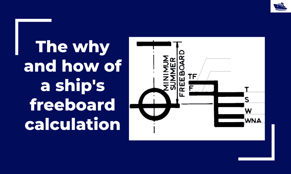
The why and how of freeboard calculation of a ship
Introduction Freeboard is a common term used in vessel operations. Freeboard is the smallest vertical distance between the waterline and the freeboard deck (generally the upper deck) along the length of the vessel. The term ‘smallest’ is of significance, as the height...
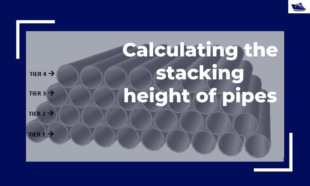
Calculating the maximum stacking height of pipes
Introduction Pipes (or linepipes or joints) are used for multiple purposes and locations in the maritime/offshore industry. Onshore and offshore pipelines are used for transportation of fluids on land, over and underwater. Pipes are fabricated in an onshore facility...
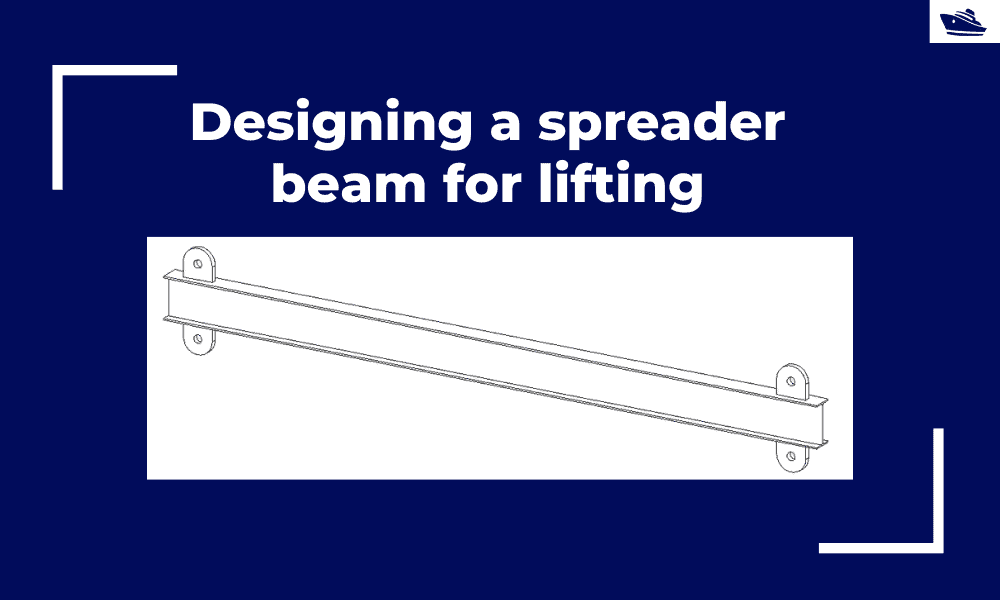
Designing a spreader beam for lifting
Spreader beams are universally applied gear which is widely used in various types of lifting operations, onshore and offshore. In this article, we will explore the design of a basic spreader beam and see what design checks are needed to establish the suitability of a...
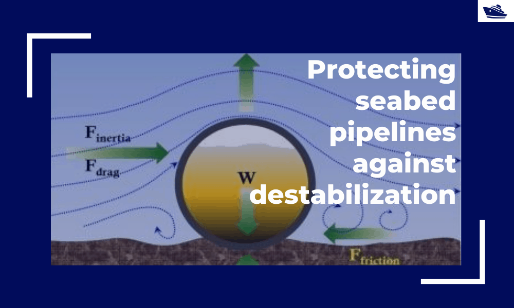
Protecting the seabed pipelines against destabilization: Identifying and qualifying the risk
The Philosophy Cable hydrodynamic stability is one of the most fundamental design topics which are addressed by cable installation engineers. In its simplest form, a simple force balance approach may be considered to ensure that the cable is not displacing...
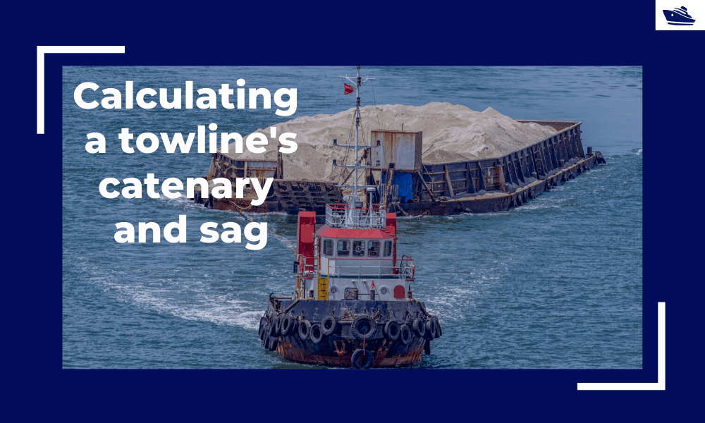
Safe Towing: Calculating a towline’s catenary and sag
Introduction Towlines connect a tug to the vessel being towed and are defined by multiple characteristics like Weight, Diameter, and Stiffness. The tension in the towline during the towing operation is not static but keeps varying with the distance between the tug and...

many thanks